14mm would be tight. Right now everything on that pcb is inside of a 14mm invisible circle around the center. However, 14mm is the outside diameter of those boots, so inside the button is probably more like 12mm. I could do a simple one to fit that size, but not one of the more complicated ones I’m going to work on tonight.
[/quote]
You can definitely get them down low. I helped Dale with resistor values to adjust his special editions. He got them down to 0.14ma draw. I recommend the 50k pots. On my board you can use just one pot, but it’s a little useless without the mini slide switches.
[/quote]
Why is it useless without the switches? I would not mind a low draw all the time… Has not hurt me yet.
I’m looking forward to see what you’re going to work on. I’m going outside now, walk around with some lights. Have fun!
I meant on the Rev4 and Rev5b boards. They need the switch populated to complete the circuit and work at all. I still have lights with Rev3 boards too and they work great.
Rev5b Osh links have been taken down to make way for an improved (and much more complicated) version, hopefully tonight.
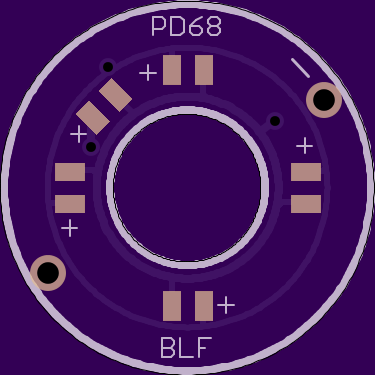
Alright, who wants to guess why there are so many pads for this one?
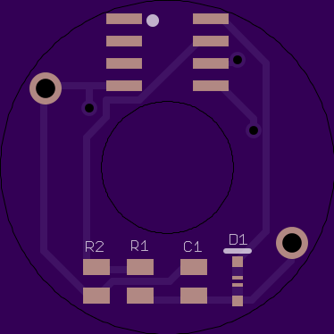
Or how about this one?

But, what controls it or for that matter supplies enough power to it?
ehhh not exactly.
Btw, I had to go to 0603 pads for that top one to get it to fit inside the 14mm radius.
Guess away people, I’ll explain the top one tomorrow. The bottom one should be pretty self-explanatory
I finally got mine working for the most part. It was the 100k pots. The 10k pots are working great. After the light gets heated up really good at the end of a turbo run, It will jump low-hi-low-hi-strobe-bike flasher-beacon-... But if I drop to a lower mode or shut the light off for 30-45 seconds it cools down and everything goes back to normal. I'm using 200 ohm bleeder resistors still so maybe bumping that back up to 4-600 will help?
I measured parasitic drain at .06mA, then the lowest I could get the LEDs to light up the amp draw was .16mA, then with the LEDs as bright as I could get them the meter read 1.9. I set it to around a .5 mA draw and it seems about perfect. Not too bright at night and very faint in the daytime.
Wish someone could make the LED lid up in pulse or beacon mode instead of constant on.
Presuming the attiny works ok in the tail then you’re likely to see a beacon option. It would save power to keep the attiny asleep most of the time, only wake to check voltage and pulse the led.
So many pads for a separate resistor for each led? (first board)
The question is does the Attiny work when powered through the bleeder resistor? (second board)
I’m going to guess that you have gone mad?
We might be getter off with the MMU version of the 13A to save spave. The firmware would be easy just take the hat check and add a sleep part to it
HELL YEAH PD!!!
My guess: RGB LEDs? Mini 6up Optic as a switch? Running light a.k.a Knight Rider effect? ![]()
Would be cool if you could have a switch that switches “modes”, Battcheck as one mode and a dim breathing effect as another. I must still be dreaming.
Leds are controlled all as one from looking at the board. So no Knight Rider just yet. But if the attiny can run stable in the tail then it’s an option.
Each led has it’s own resistor. So you could do something like having many different colors. The brightness of each would be dialed in by it’s own resistor so that they could be adjusted to all be the same visual brightness. No one color overpowering the others. Would take some patience to adjust the vaules.
Yeah, my guesses weren’t meant to be that serious… BUT I’d love a Knight Rider Tailcap. 8)
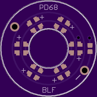
Yes, that’s pretty much spot on. This is how you would configure it for that:

But the reason I jammed all of that in that shape on the top was so that you didn’t have to go to all that work of dialing in resistor values if you didn’t want to. You can also configure it this way:

Both of these configurations are basically self-contained, so it can be plopped on any stock switch and pcb that it fits on, it doesn’t require special connections on the bottom pcb. However, you can pair it with one of the potentiometer boards if you want that kind of control. For instance, you could use resistors to level the brightness of multiple different colored leds on the top board, but still easily adjust overall brightness with the pot.
Rev5.1 Oshpark Link Note: 0603 sized pads
……………………………………………………………
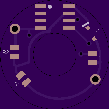
Rev6
This uses the normal Attiny13 so it should be able to do basically anything our programming wizards can come up with. The only question I can think of is if the Attiny can work on such a low power level, and how much power would the mcu itself actually take. With the layout I tried to keep it the same as a normal driver. The voltage divider resistors are on the same Attiny pin they usually are, and I have the LEDs connected to the usual output pins. I’m hoping that means when I get these first boards I will be able to use TK’s existing batt-check FW to do initial tests on how well the Attiny functions, then if all is well we can write some code for pulsing or beacon or whatever.
As far as the outputs, you could really do it a million different ways, so I just had to choose something for this first gen. On the top the four led pads are connected to pin6, and the fifth LED is connected to pin5. My thinking is you could have Green/blue/whatever LEDs on the main pads, constantly on/pulsing/beacon/whatever then the fifth led could be a red one that only comes on/flashing when the battery gets down to a certain point. I’m looking forward to everyone’s thoughts.
Edit: Now that I’ve explained all that, I just realized I need to re-do the layout of Rev6 so that the board will actually fit down over the switch * facepalm*
Clever lay-out with/without individual resistors!
Would the backside of the topboard need clearance where the switch is in contact with it?? (or did you just mean to say that in the edit above?)
With the bleeder resistor in series with the tail-circuitry, eating some voltage, I can imagine that the voltage divider resistor values and/or the voltage sense software need tweeking.
Yeah, I made sure to push the mcu out far enough, but I forgot about all the other stuff. I was just trying to get to bed last night. Anybody know if we really need the input capacitor and reverse-polarity diode for this application? If not I’ll just remove them and get a cleaner looking board
that’s what I’m hoping to do with TK’s batt-check before begging someone to make an actual firmware for it
Ok, Rev6 should be good to go now.