Never fear Gunga; AA compatibility will certainly show up before anything else!
I’m very encouraged by HarleyQuin’s results and I look forward to playing around. My hands are tied until donor drivers show up with PAM2803’s. Tracking isn’t showing much, hopefully they’ll show up any day now.
Just finished an order for 3 Nanjg 110’s from RMM. Also now have a couple of the dirt cheap Xpe boost lights someone was borrowing from. Now all I need is time. I’ll try and find the time to open one up and have a look at the driver.
Ideally we don’t stack/parallel diodes, but yes it’s possible. They must be “thermally coupled” to avoid death. In practice it seems that installing them side by side is a good enough thermal couple for us. With that said, I’m not sure why we’d need to with the BAT60A diodes mentioned in post #35.
Some cheap sourcing.
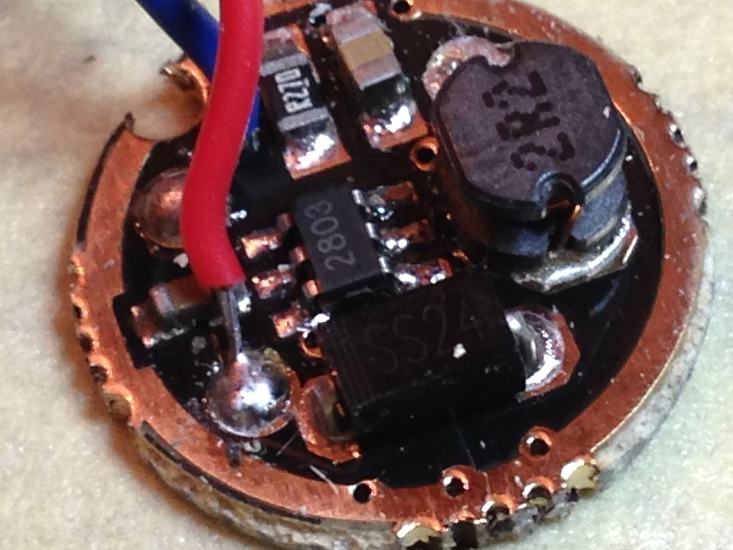
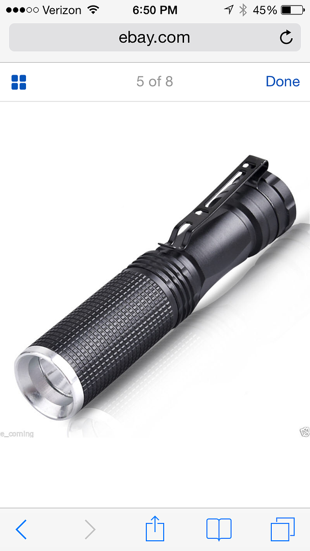
A member earlier posted a thread on This AA/14500 light from eBay which was $2.58 each when I bought 2 last month and contained this driver.
Removable threaded pill so easy to mod and you get what looks like a nanjg 110 and host for not much more than the driver alone. Bought it mainly for swapping into Incan minimags after reducing current for 2xAA to around 150-200mA. Switch doesn’t look worth much but lens and reflector ok to use.
No problem. Flashlight circuits can be pretty tricky stuff. I often resort to grabbing a sheet of paper and drawing the circuit quickly when my common sense fails me… but to be useful this practice does require a basic knowledge of how the circuits work.
IMO boost circuits are one of the trickier-to-understand circuits we use here. The idea that we could literally short the battery through an inductor thousands/millions of times per second (bypassing the LED entirely!) and still achieve an efficiency >50% is pretty crazy. Boost circuits can actually be very efficient (>90%)… we just won’t achieve that with this driver.
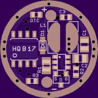
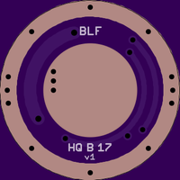
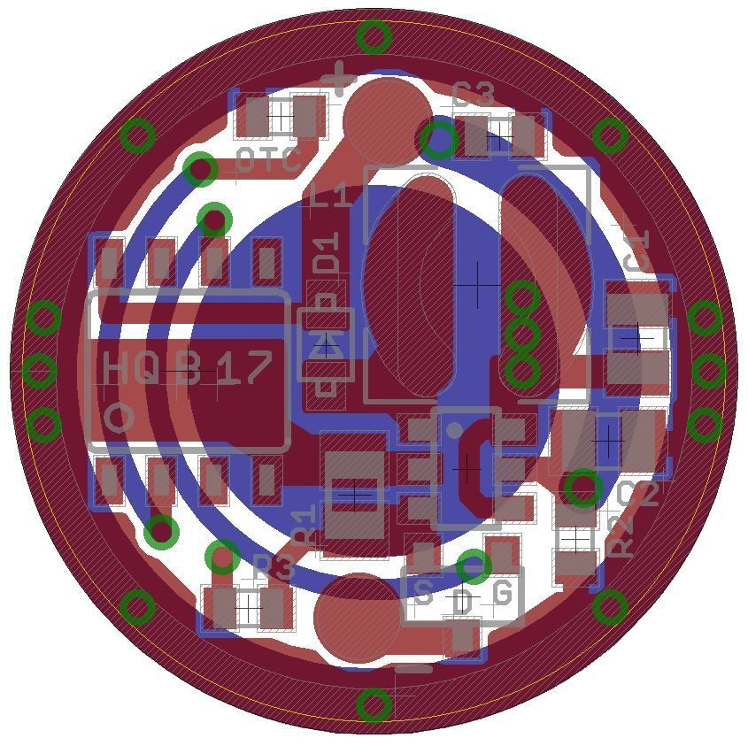
17.6mm actually, the yellow ring shows 17mm
adapted for larger toroid (5.8 x 5.8 mm)
additional info is to be found in the HQB15v1 post and the HQB15v2 post
Partlist
(see post#26 for more info on the parts)
EDIT: The values below are derived from the successful build of the 15mm board, but my very well vary. It’s all in development at the moment.
Switch: PAM2803, SOT-23-6
L1: min. 2.2yH, 4.7yH recommended, up to 5.8 x 5.8mm, 6x6mm might work
D1: BAT60A, SOD323 (Mouser) (Farnell)
R1: 0.120Ohm, 0805
R2: 150kOhm, 0605
R3: 33kOhm, 0605
MCU: ATTiny13A-SSU, Package 8S1
OTC: [1yF], 0603, X5R or X7R [OTC not tested yet]
FET: (from FastTech driver)
Note on C1-C3 capacitors: The values of the PAM2803 datasheet are in all probability too low for our purpose, as we add modechange and PWM to the circuit. The values below are the ones I successfully used with the 15mm board (post#84). I took the highest capacitor values I could source. Less might work; use carefully.
C1: 10yF, 0805, X5R
C2: 20yF, 0805, X5R
C3: 4.7yF, 0603, X5R
C2 and C3 are by design in parallel (C2 as close to PAM2803 pin5, C3 as close to ATtiny13A pin8). I added C3 to be able to increase capacity with a second capacitor. Smaller values might work, populating only one might work; use carefully.
Increasing the size to 17.6mm is to make soldering the driver in place easier, is this correct? In reference to the 2oz/0.8mm boards OSH Park says “Castellations are allowed, but not officially supported.” That could be an alternative to oversize boards. We’d probably need to contact OSH Park support to see precisely how castellations should be indicated of course.
Bah humbug. If you want LVP so badly just air-wire it with 1/8w resistors. I don’t see “extra” space on HQ’s board.
Then fix the firmware to not go into LVP with a NiMH/Alkaline/Lithium-primary/etc. I don’t think that this task will be complex, but it must be done.
EDIT: Just in case you are not aware… LVP isn’t needed for operation with AA cells such as Alkaline, NiMH, and Lithium primary. LVP in flashlight drivers is to protect Li-ion cells from overdischarge.
As we know Oshpark does not deliver copper to the very edge of the driver. There are 0.3mm missing.
I oversize drivers for 2 reasons:
- making them easier to solder and
securing contact for drivers I want to press fit.
Castellations as I understand are copper plated half-holes at the edge. I’m afraid these half-holes would simply be deprived of 0.3mm copper as well… I think it’s a manufacturing process/problem.
I had tired several changes in eagle to avoid this: Smaller Dimension(20) circle width down to 0.001; Milling(44) instead of Dimension(20); Oversizing the Top(1) layer so it’s larger than Dimension(20). All to no effect.
So I simply oversize 0.6mm (pay the additional 7 cent per 17mm-board) and file down. With a dremel and this sanding bit it’s done in seconds.
.
To the Li-Ion issue.
There is a difference between surviving a Li-Ion (4.2V) and being designed for it. The PAM2803 is not designed for 4.2V Li-Ion and I will neither use nor test it. For single Li-Ion a linear driver is a much better option.
LVP would limit the options for those cells, this driver is intended for, which well includes all kinds of primary cells from 1.5V to 3.0V.
LVP, if you gotta have it, just glue the voltage divider on top of the mcu. You’ll still need to choose appropriate new values and add the programming. Do that before you glue and air wire.
How will the programming need to differ from other 13A controlled drivers? Would it be possible to swap a 105C mcu and leave LVP unconnected? Build one and see?
The only difference is that we’d disable LVP when building the firmware. From HarleyQuin’s work earlier in this thread I think it’s safe to say that standard PWM freqs are OK. Lower PWM freqs could be required to eliminate buzzing/whining. I still don’t have anything built; my donor drivers have not arrived from FT yet.
I can’t remember = build one and see. Worst case scenario, simply tie LVP pin to Vcc. Leaving the pin ‘floating’ could lead to unpredictable results…
This lfpak33 sold by RMM seems to have good specs too.
The lfpak33 is similar in size to the others but with obviously a different footprint. I don’t know if that’s advantageous or not.
 light from eBay which was $2.58 each when I bought 2 last month and contained this driver.