I got some that are 0805 footprint. Slowly change colors, but stay on red the longest. Looks interesting sitting on a shelf. I think it needs more voltage than the standard LEDs.
On a different note, have you considered putting some more of the consolidated knowledge in the first post?
Typical resistor values that work with different color LED’s, etc? Makes it easier for people who have not been following the thread from the start.
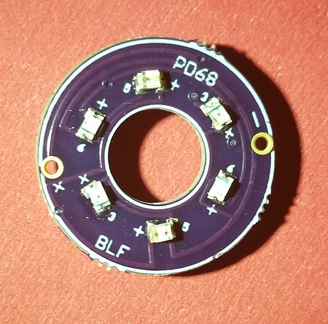
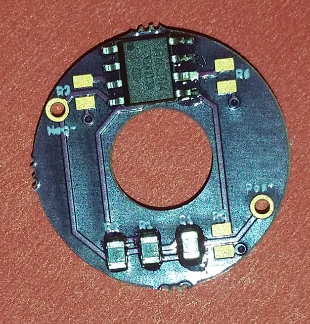
Got most of the smart board built today. But, when I test them onboard with diode check on my meter only the pair 4 will light. Pairs 3 and 5 appear to not be good onboard, if I remove them and diode check them they light fine? I do not have the resistors on the board for any of the LED’s, I plan to solder small wires in place and breadboard it so that I can find the correct resistor values. Not really sure where to start, maybe 2 to 4K. I will also breadboard the power supply to the board so I can get the 560 dropping resistor in-line with out doing weird things to a light.
It can blink fairly easily. It cannot fade without an awful lot of extra effort though. The controller needs to spend most of its time in power-saving sleep mode to avoid drawing extra power, and the LEDs are on pins which can only be on or off. The controller can’t do any PWM while it’s asleep.
The dumb boards have resistor spots anyways, so you can have 20k resistors on the ring and a pot in series down below to dial it in, or just skip the pot and use the resistors. My M6 just had a lot of room in the tail area, so I threw the pot in there.
I try to keep as much of the non-subjective info as possible in the first post. That said, I actually recently removed resistor values from the OP because I’ve found it depends on a few variables, the biggest of which is the person’s preference for brightness, and also what board design is being used. I think it’s better for each user to buy one of the assortments of resistors or some potentiometers and dial it in for themselves.
I added this line to the first post:
“Depending on what LEDs are used, what board is used, and what brightness is desired, the required resistance value can be anywhere from 1k - 50k+”
Hey Pilotdog, would it not be a bad idea to leave a value posted, while not optimal for every situation but one that would make light in 95% of the builds?
I looked in the other project threads and did not see if you had found a suitable replacement seal for the metal S2 tail cap rubber that you had removed.
Made any progress on a permanent replacement?
In my blue S2+ I used a piece of ziploc bag, and it actually works pretty well as long you don’t rip it during installation. At the recommendation of another member, I’m planning to replace the ziploc with part of a latex or nylon glove
Quick newbie question - I just received my first shipment of these boards and am doing my first build. I haven’t even started on a tailcap yet but in having issues with the bleeder resistor. Driver is a normal Qlite from Richard, so I should be able to stack on C1, yes? But if I put a 560ohm resistor there I lose modes. The driver won’t change modes anymore. I think C1 isn’t bleeding down. So I upped the value to 1k with no change, still don’t have modes. How high can I go and still have a functional tailcap? Any 1st hand experience with this driver?
I’m looking forward to new driver designs which aren’t so finicky about these things. We can get all these new features to work, if they’re very carefully adjusted, but it falls over very easily. Hoping for something more robust.
Ummm… its GuppyDrv, so I guess so. I’ve never built one of these drivers. Richard sells them cheap enough I’ve never seen the need. So I’m not all that familiar with how they’re laid out. The cap is actually labelled C1 right on the board though, so that’s why I assumed it was the right thing to do. You can see it in Richard’s image here:
Obviously this isn’t working so I’ll probe around for other locations, but I’d like to understand why this wasn’t the right place if anyone has some insight.
Pilotdog68 was right, it did sound like you were stacking on an OTC… but it doesn’t look like you were stacking on the OTC. That sure looks like what we typically refer to as C1, the decoupling capacitor the the MCU. I’ve never taken apart a QLITE before, so I checked that cap with my DMM just now to be certain. It’s definitely the correct component. EDIT: it’s definitely the decoupling cap, but…
… err, sorry, I haven’t followed this entire thread. It’s probably not the correct place to stack the resistor. Unless I miss my mark, it C1 would be correct on a current-generation FET driver, but is not correct on a classic Nanjg / QLITE setup where C1 comes after the protection diode. Another user will correct me if I’m wrong, but you probably want to connect BAT+ directly to GND using this resistor.
Thanks guys. I don’t claim to fully understand all of that but I think I got enough of it. I’ll see if I can find a spot to just connect directly from + to gnd like you suggest.
I have never had to add the bleeder with Richards 7135 driver. There is an inherent bleed in the driver as well as most of the 7135 drivers I have tested. I have lighted switch boards working with 3 to 8 7135 boards and most of the FET and FET + 1 boards that are common here. I do use a 560 ohm bleeder and have a mix of boards with 22k and 19.1 k resistors in the voltage divider circuits. I do find that braiding the tail and head springs do make the boards a tiny bit brighter.
I am hoping to have one of the spinning boards working on a breadboard in the next couple of days, this way I can determine the correct balance resistor values. Had one built, but would not work. Pulled all the parts off and found shorts in or on the board at led3 and led5, but led6 would work and the software did load and run!