my first soup can mod: 9xLG385nm

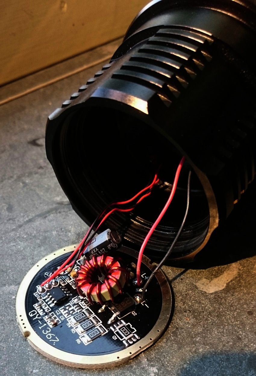
Apparently I'm a principal person, I bought this Bestfire 9-led light last year may from dx and upon finding that the leds were not the promised XP-L but some chinese junk leds, I went to great lengths to get the light returned and get my money refunded . Then a few months later I bought it again to be used as a host. and today I did the mod, my first soup can mod! The host is neat and well-arranged, lots of opportunities to improve it, with everything accessable: better leds, thicker led-wires, bypassing the R100 resistors before the FETS, bypassing the bottom battery springs that are easily accessable. One improvement was already done for me: the one FET-driver of last may has become a two-FET driver in last november's copy, ledwires were also already a bit thicker:

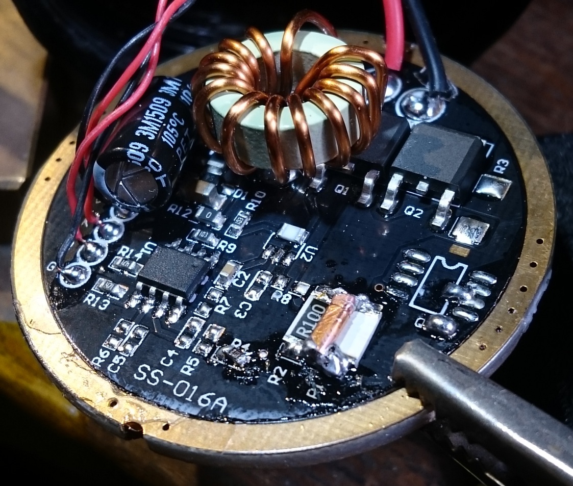
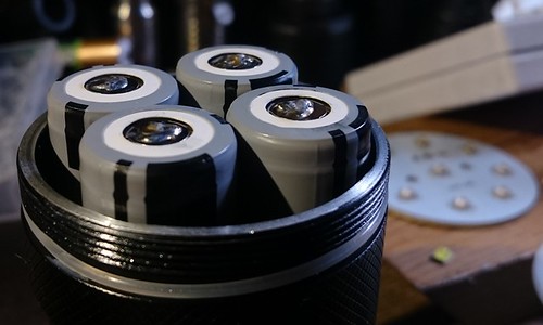
Left the one-FET driver, right the two-FET driver (note the R100 bypass with piece of copper already done)

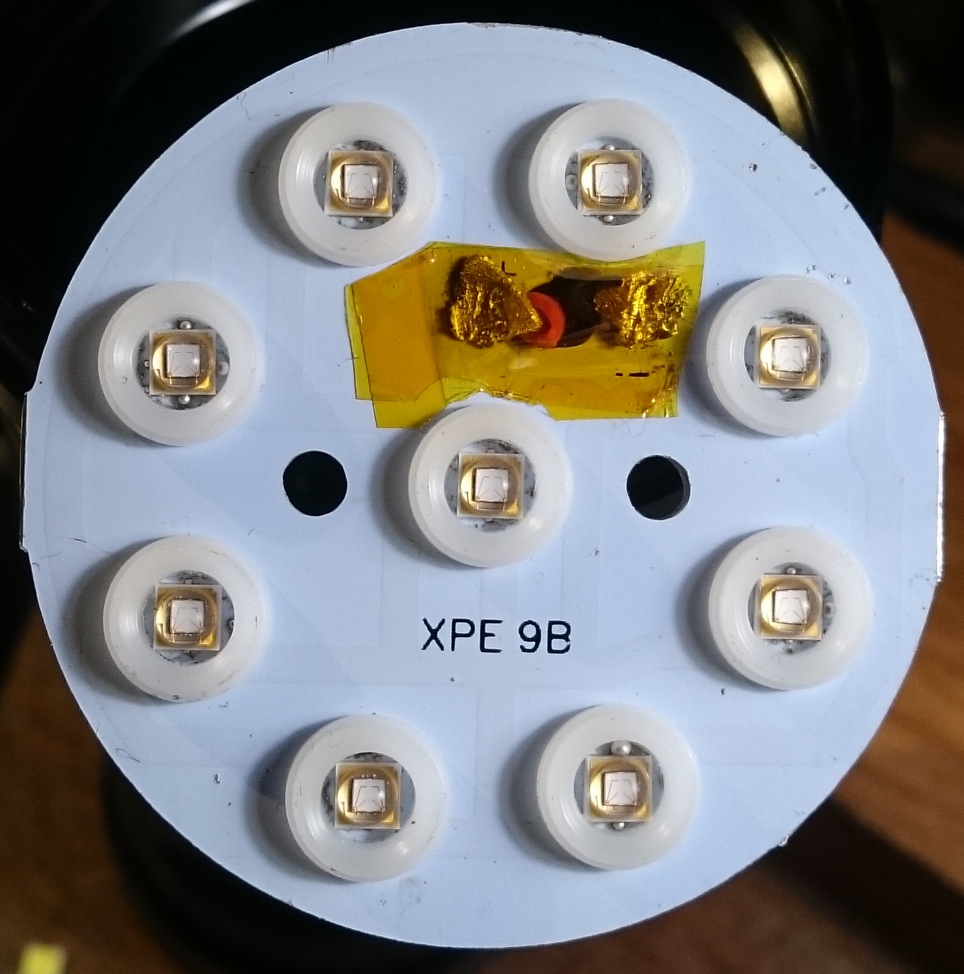
I first started with replacing the leds, this was going to be a 385nm mega-flooder. I bought 10 LG 3rd gen. 385nm leds on Aliexpress for this mod. I want 1A max per led (for a test of this led on a copper board, see https://budgetlightforum.com/t/-/36866 ), so I did not bother with copper boards. I love watching reflows so I made a video of the swap, it took longer than I thought, I did not realise that 9 leds is quite a number to replace:

It worked first time, jay!, so I was very curious of the ledwire current in the further stock light. I love my new clamp meter for the ease of use . I got 4.67A already on four NCR18650BD batteries, that is 500mA per led, not bad. I had to add blobs of solder on top of the batteries to have them make contact to the driver:

Then I bypassed the two R100 leds on the driver that were in series with the FETS and the current went up to 6.42A, 700mA per led. Then I replaced the ledwires with 18AWG silicon wires and got 8.6A, almost 1A per led which was the goal, any higher I would not trust without DTP copper ledboards. No spring bypasses needed

Now it appeared that when closing the head, the ledboard by a hair does not touch its shelf on the host, the board-reflector assemby hangs on the outside of the reflector. So a spacer was needed to get the ledboard touching its shelf. I do not like to use chunks of copper, but I did not have anything else than copper. So enter the (modest 1mm thick) copper disc:

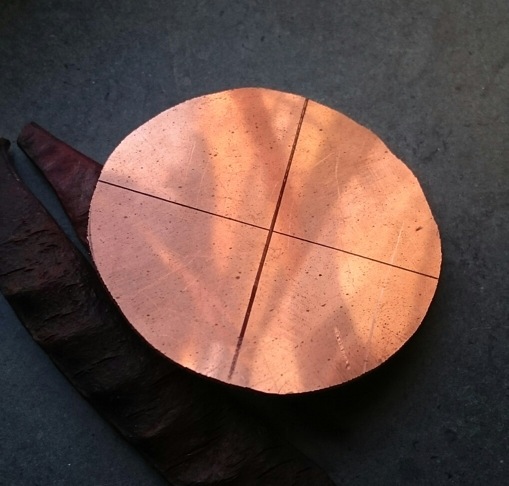
Sanded, holes made and attached to the ledboard (no thermal paste):

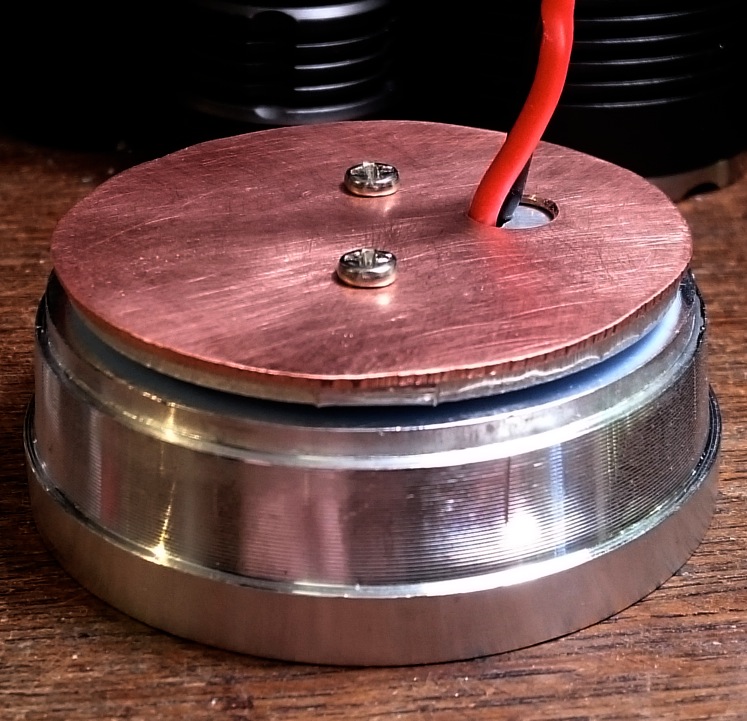
A tiny bit of thermal paste was applied on the shelf to make good contact and everything assembled. Done:

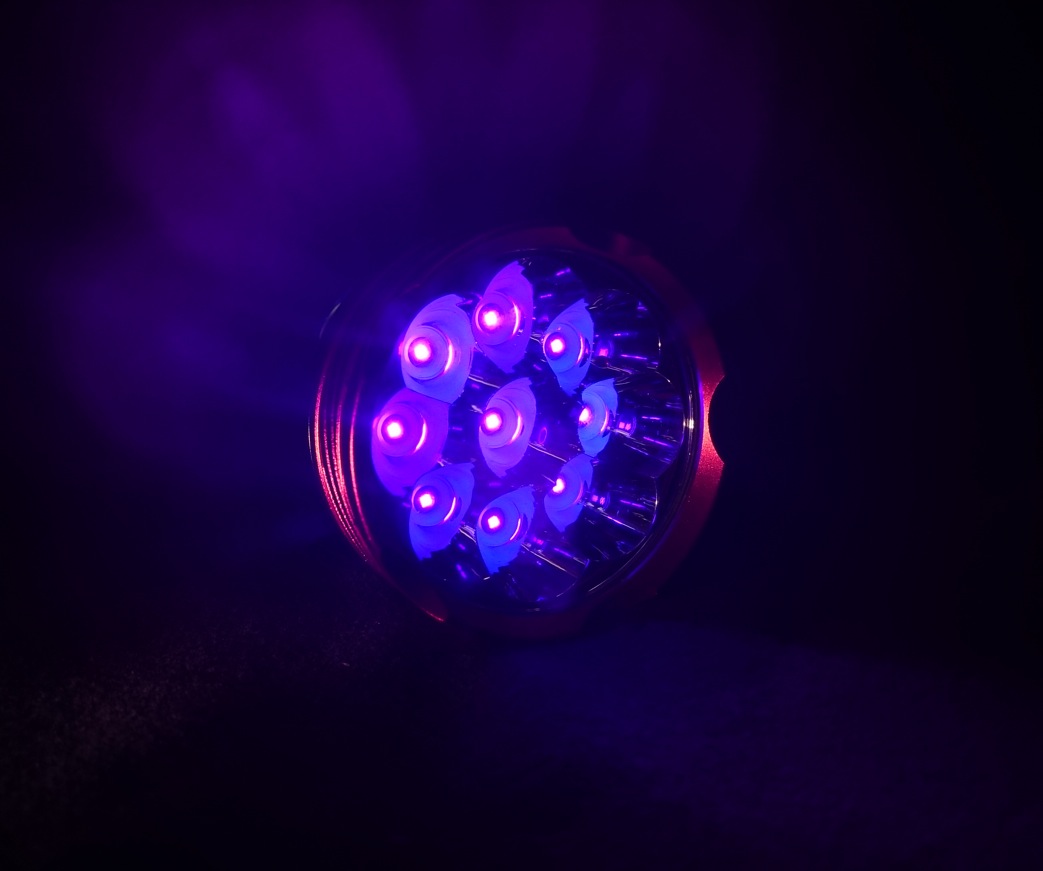
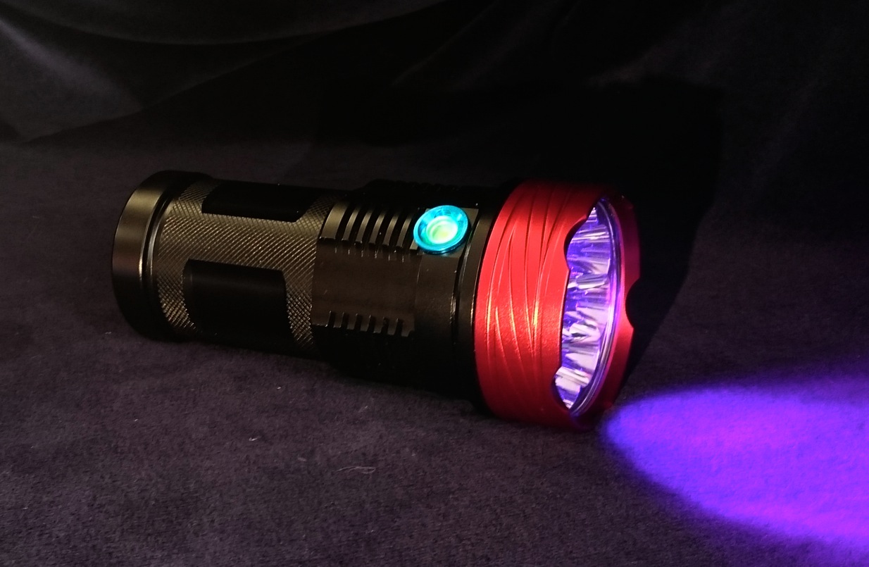
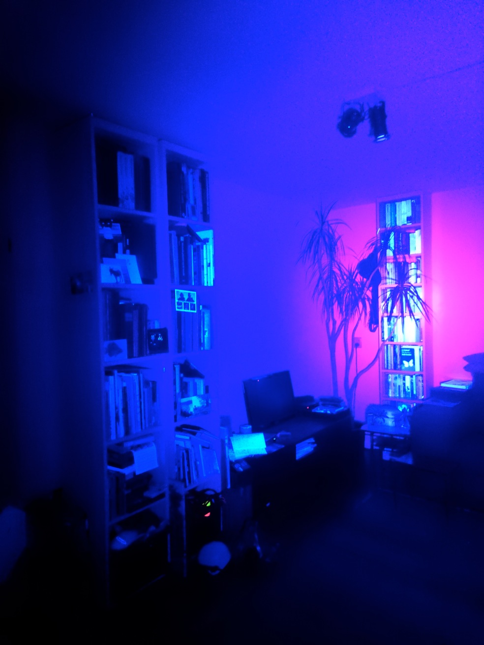
The light projected on the wall with a (overhead projector) lens:

It is a LOT of UV-light:

So now what to do with it?, dunno, it was fun to make. Perhaps Hestbech, if he reads this, would like to try it for his amber-searching?

Anyway, I ordered another one of these hosts for a mega-warm-white-flooder

Thanks for reading.

Nice. Going by the beam shot it doesn’t look like it would benefit much from a lens filter -http://budgetlightforum.com/node

Haha, that looks freakin awesome.

WOW.

CSI here we come .

Oh man. Does the bounce-back from white walls hurt your eyes at all?

awesome, that projecton, try sell it to a museum!

Sweet build. Now if a vendor would make an affordable filter that fits that light, a new trend in UV flash lights will started.

Nice. The overhead projector beam shot is crazy.

The use of a filter for 365nm leds is to filter out the white light that the leds produce as a by-product, the 365nm light is completely invisible.

385nm leds is a different case, there’s no white by-product (which is a good thing), what is distracting is the 385nm light itself, your eyes are slightly sensitive for it and with these high outputs it is clearly visible as a purple glow. You’re not going to filter that out because 385nm is what the led is about. You can use yellow glasses on your head when using this light, it will remove the purple glow, but also makes the world a bit yellow of course :slight_smile:

BTW, I use polycarbonate safety glases with this light, my eyes would be dead without them. Yellow glasses are even more friendly for my eyes.

Nice, a high powered UV light! Makes me want to build my own, but only in a triple form.

You’re right. I was shamelessly plugging a product request to gin up demand for such a product. I would like to make a 365 UV flooder with my 10 budget 365nm emitters I already have.

Good work on the mod djozz.

Are you certain that the new driver is not a buck driver? (and maybe the old driver too?) The new driver appears to include a large coil, a large capacitor, sense resistors, and two DPAK items. Since diodes are available in DPAK layout the driver could easily have an FET and a diode on it. Together a buck controller IC, this completes the list of normal parts included with a buck driver.

See ImA4Wheelr - Driver Info: HX-1175b & HX-1175B1 (Pic Heavy) for another example where we initially thought there were two FETs but it turned out (post #8) that it was a diode and an FET.

I only know some driver basics so I could nevertell anything for sure , at least the batteries are parallel and the two ‘FETS’ are wired in parallel, with the two R100’s between ground and what I assume is FET-source, the FET-drain is the led-minus, the thorroid is connected to led-plus. So I assumed that it is direct drive, and I vaguely remember comfychair adding a thorroid to a direct driver as well for some reason (suppress nasty spikes?). I closed the light up for now, but I’m prepared to open it again to make better pictures of the driver if there’s interest and it helps understanding what is going on.

Btw, it is a simple high, low, off driver with low frequency PWM, electronic switch and a small green on-led in the switch. I like the simplicity of it but it is not anything advanced.

Don’t bother opening it up for that reason. We already understand how the inexpensive Chinese buck circuits are laid out, so if it’s one of those we wouldn’t learn anything.

If the FETs are truly wired in parallel and there is no schottky diode then it is certainly just an FET/DD/PWM driver.

The inductor/coil does help with spikes. We’ve seen single cell drivers constructed both ways. (The initial 3-toroid SRK drivers were in fact buck setups for example.)

Awesome mod Djozz, what a crazy flashlight. Your hands shake almost like mine :smiley: .

Thanks! I hope you will never find my first BLF reflow video, let’s say that I am extremely steady now. :-/

That thing looks like it would produce an instant headache :cowboy_hat_face: :cowboy_hat_face:

Nice build :slight_smile:

Thanks djozz. Nice mod as well as a very good video on reflowing multiple leds. Is there a thread on your little home made hot plate?

Thanks! Hmmmm, how I made the heatblock is in the same ancient thread as my above mentioned terribly shaky first reflow, so I’m a bit hesitant to reveal the link……, oh well, here it is, don’t laugh :-/ link

Would I be out of line to ask how you were able to reduce your shaking?