With that high of draw on a Rev5, it must be pretty bright, eh? Or maybe the LEDs are a little inefficient, it doesn’t look blindingly bright in your pictures.
emarkd, did you ever get yours dialed-in?
With that high of draw on a Rev5, it must be pretty bright, eh? Or maybe the LEDs are a little inefficient, it doesn’t look blindingly bright in your pictures.
emarkd, did you ever get yours dialed-in?
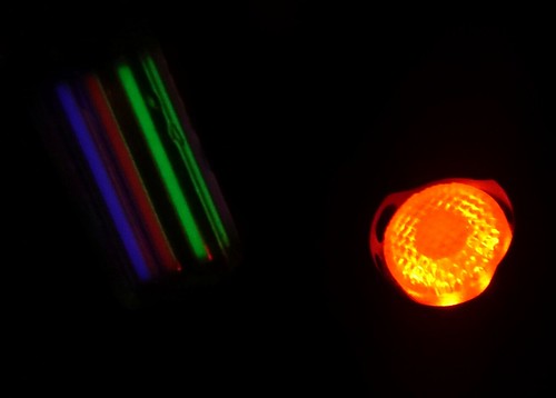
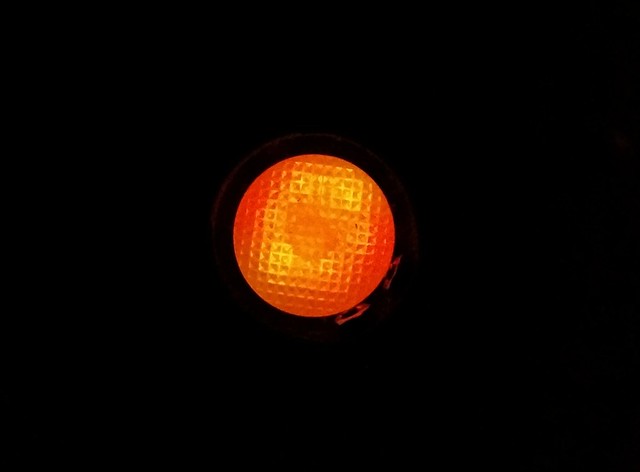
It appears about as bright as that one blue led of the stock tail. In other words, in the dark it is a good bright indication light visible from quite a distance but not disturbingly bright (the orange colour helps with that), it can be much dimmer and still be useful.
Here it is next to my keychain fob, that has three big bright trits (way brighter than the small ones in my Ti Reylight):
Hi guys!
very nice X5 you got there!
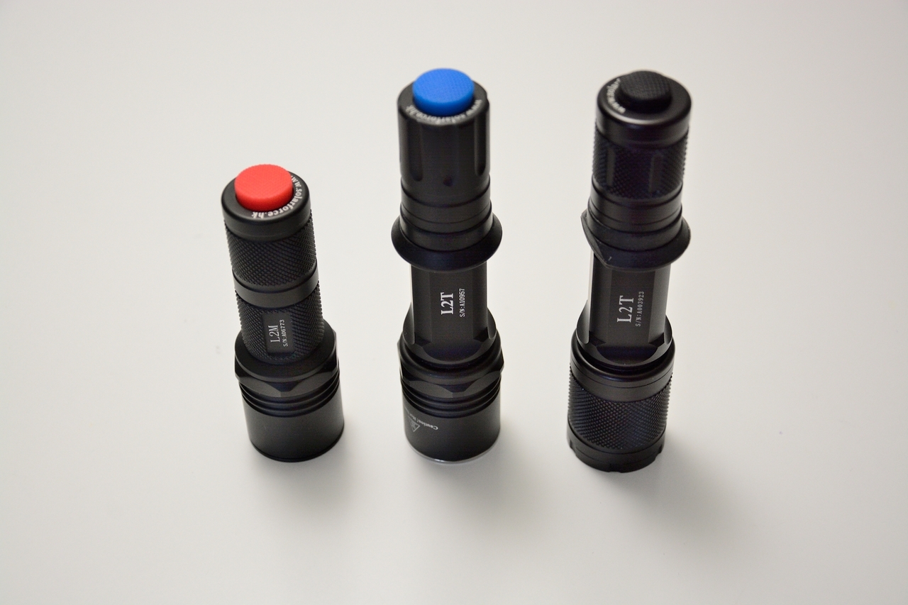
like you, I want to upgrade some Solarforce tailcaps. I can’t help you with the S2+, maybe someone else can chime in here. I opened up the three Solarforce tailcaps I’ve got and found that they differ. My L2T is one of the first batches, it has the glossy type ano, smaller tailcap boot and smaller PCB in there. It’s about 19mm, maybe the 19mm LTC-board would need a little filing. My L2N and L2M have similar tailcap internals, same boot size, about 21mm PCB. Notice, all these lights have the forward clicky installed.
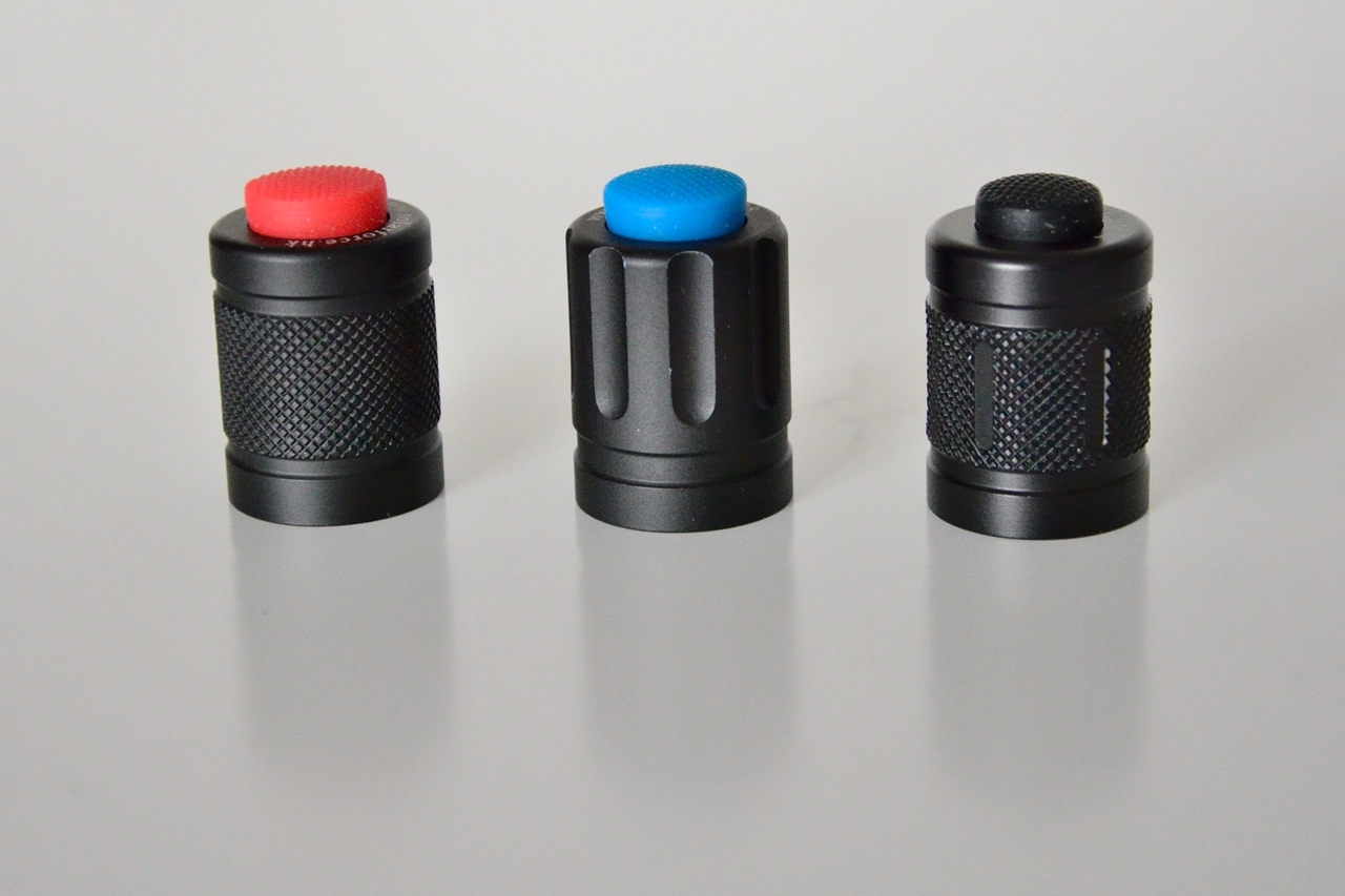
Some pics:
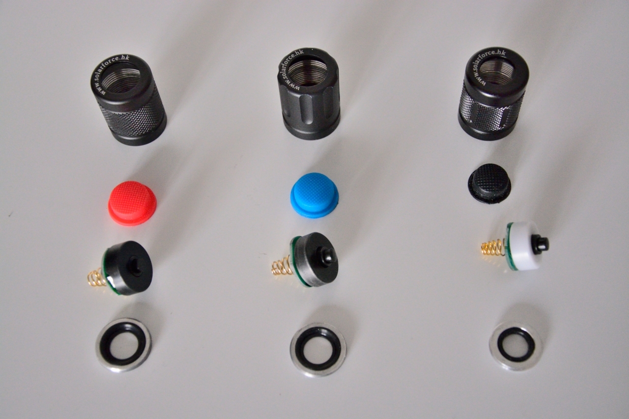
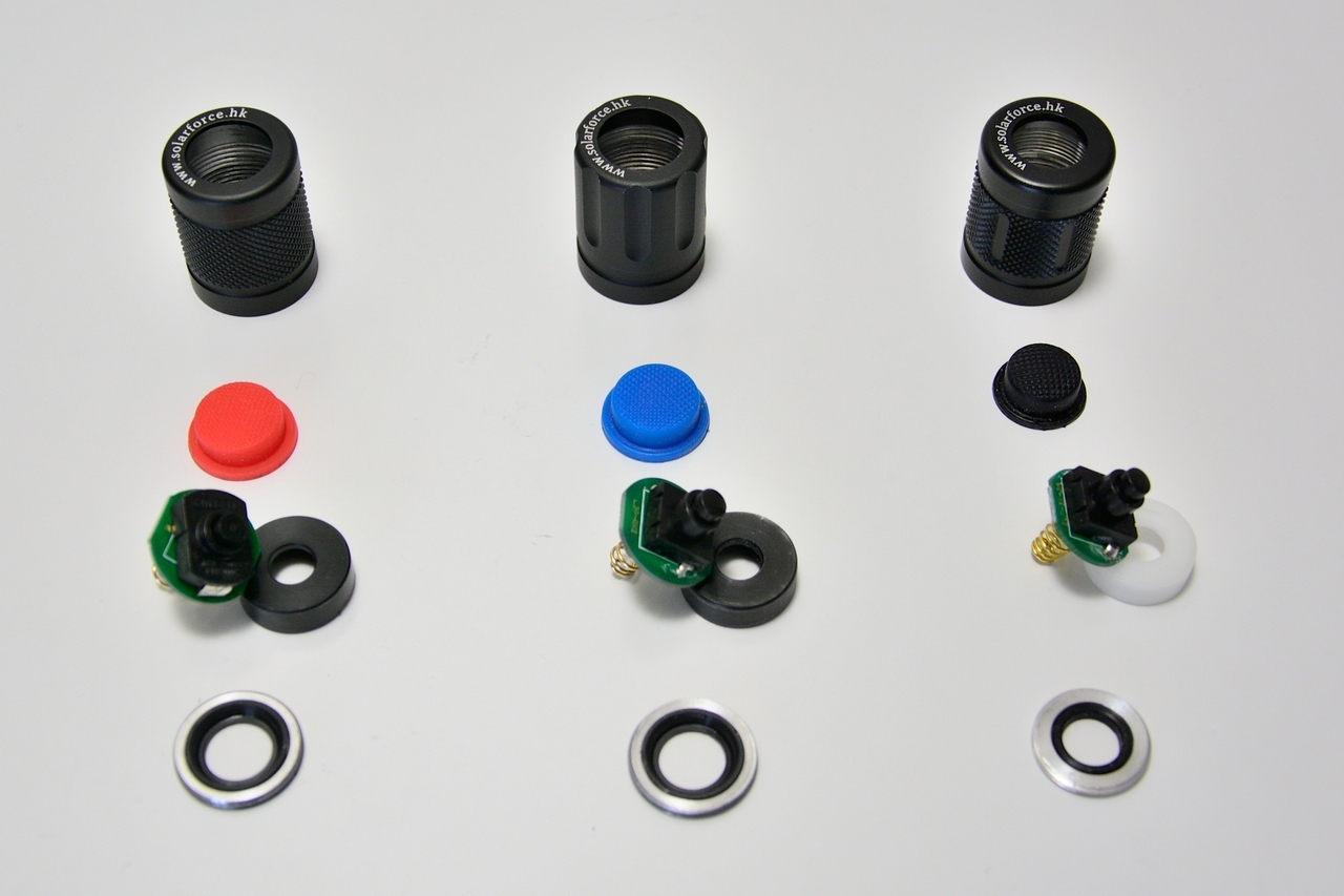
Obviously I converted the L2M to reverse clicky
I’m very sad since I found out the L2N is discontinued. Well, at least I got one. But it’s such a nice light to play Solarforce lego with… :-((
Pick one up if you find one for a acceptable price…
Also, the spare switches are gone from the Solarforce site.
@PD68
What are the specs I should watch out for, when searching for some nice LEDs for LTC purposes? 0603? current rating?
The L2n is discontinued?? That was my favorite one… guess I won’t be selling the one I have left.
I have had LTC in multiple solarforce tailcaps, but none with the Rev5/6 ring design yet. Previously it was hard to get the forward-clickies to fit on the board, but that shouldn’t be an issue with the ring design as long as the ring fits over the post on the forward clicky
I have successfully used a Rev4 board in an S2+, and at least one other person (emarkd) has used the Rev5.1 board, I’m guessing the smaller size.
There are a couple boards that require 0603 size, but most use 0805 size pads. You can use 0603 on 0805 pads though, which is what Djozz has done.
Yes, L2N is discontinued, I asked them… Couldn’t resist and picked up a spare L2N from KD, I hope it’s genuine.
Thanks for answering my question about the LEDs. What kind of current rating would you chose? I’m currently packing some stuff into my mouser cart and can’t decide what LEDs to get. For example, blue Osram 0603 LEDs, which one should I order, 2mA, 10mA, 20mA rated? Or even higher?
I buy my LEDs from Lighthouse (linked in OP). For example the blue 0805 is rated for 20ma and luminosity of 120mcd. The red is rated 20ma and 180mcd. I think what you want is the highest mcd possible.
maybe the lower power rated will be more efficient at the lower power we give them (less than 1ma)?
Lighthouse also has theirs rated as “LED Brightness Class: Super/Ultra/Extreme”, but I don’t know if that’s actually some kind of standard or if it’s just marketing hype.
Thanks PD!
That’s an interesting point. I will be digging through some datasheets and eventually someday I’ll complete that mouser order… ![]()
You want the highest Luminous Intensity. That usually gets you the highest brightness even at very low currents. For example most blue 0603s are rated at 20ma but the Luminous Intensity of different ones range from 3.6 mcd to 180 mcd. Best to pick one from the higher end. Though you should double check (using the datasheet) that the mcd listed is for the actual part number mouser is selling. Occasionally there is a mistake where the specs listed are actually for a higher bin.
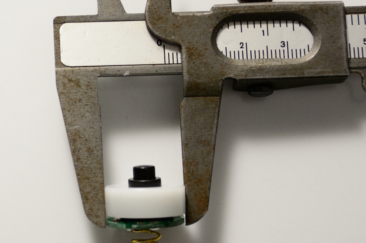
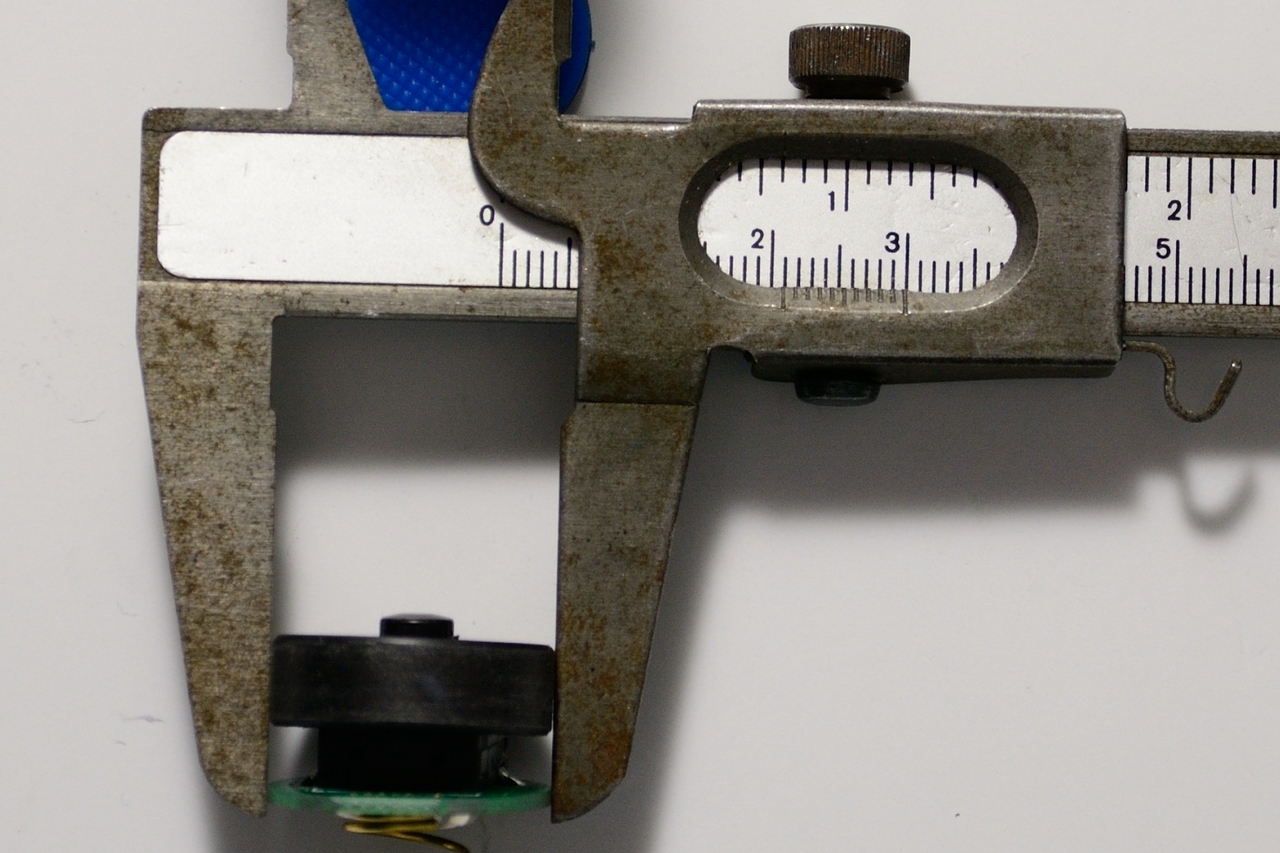
I haven’t messed with my blue S2+ again. I’m really very happy with it as-is, although the drain through the tailcap is a bit high. Still, it would take about a month to drain the battery just sitting on the shelf and I find that acceptable. And yes, I used the smaller board in there. It looks like this stacked up on top of the original switch:

I did start on my red S2+, however. Same bleeder resistor on the driver and it works great. I made a silly mistake though - I assumed the LEDs that look red when powered off would also look red when powered on. They don’t…

So I’ve gotta work on that one a bit more ![]()
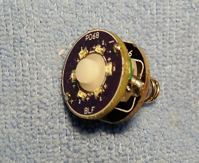
I notice there isn’t a white ring around the middle of the board there. Did you drill it out or did Oshpark print it that way?
I didn’t modify the board at all. They came like that. Here’s a shot of my whole shipment of PD-boards all dumped out on the table:

Is there some issue with them? Or is the change only cosmetic?
No, if they’re working at all it’s fine. I probably put that line too close to the edge. The “2” channel has a trace closest to the center on the bottom, but obviously it’s working fine.
I like to split larger orders into several smaller orders so I get moar stickers! They have always shipped the same time lol…
Sorry if this question has been asked or answered before. Can you make these very cool lighted tail caps for customers like me?
Thanks.
Answered in the OP: “I am not currently taking orders for them.” :-/
One reason for that is it is rarely a drop-in upgrade. Many times it requires fiddling with the driver or at least fiddling with the tailcap stack to get the light working again. So it’s usually much better to work on a complete light than just sell the tailcap parts. Shipping a light back and forth adds at least $10 to a mod.
The second reason is that I don’t have the time to build as many as I think there would be demand for, and I don’t feel right saying yes to some people and no to other people.
But like I said in the OP, I’m sure someone would do it for you for the right price.
I tried to sell one of my spares on Panjo some weeks ago. zero interest.
I’m using it to build up a C2 style solarforce to gift to a friend
Well crap! I have an S2+ that is my EDC and I decided to try out one of the new washer replacement tailcap boards. Got it build, it ohmed out well and all of the leds lit on my bench supply. So, I took the 2 led switch out of my S2+ and replaced it with this…
!
!
It lit up and worked well, for a while.
!
!
Then I lost mode switching! If I very quickly lock out and lock in the tailcap it will switch modes. But, if I half press the reverse clicky it will not switch modes to save it soul now.
What the hell? My meter sees an open on a half press with it mounted in the tailcap. I used 4.7k resistors, so now it would be seen as 3*4.7k in parallel?
Any ideas? Can a switch go bad this way?
Matt
Well, after spending more time with this… the 4*7135 in this light does not like this board even though it is currently working with a 2 blue led board. But, this board works fine in my JAX C8 Mini with an 8*7135 board. These things could lead to drinking on a bad night! It also did not work properly in the BLF X5, mode changes were wonky.
I finally got boards built for all of my colored S2+ lights.

All are the 14mm v5.1 ring boards used in place of the metal washer that was in there. Looks like this all mounted up:
All of them are using color-matched 0805 emitters, obviously. Resistor value varies greatly between them, from 5.9Kohm for the blue down to 1.5 Kohm for the red. Yes that means the red isn’t very efficient, but I didn’t build them for practicality. They’re fun! All of them have MtnElectronics 105C drivers with varying numbers of 7135s depending on the emitter in the light, and all flashed with GuppyDrv. They all work as expected after I got the bleeder resistor value worked out, 220 ohms in my case. I connected that bleeder resistor directly from V+ to GND right here:

Since I had to remove the original black rubber piece that provides all the waterproofing in the tailcap of this light, I added some nylon rubber I cut from a disposable glove. I put it directly under the switch assembly, like this:


I haven’t tested it yet so I have no idea if that works or not, but it looks…reasonable. Would probably be better without the crease in there but they all did that when I screwed them down.
I’ve shared this before elsewhere but here’s a bonus shot of the other end of these lights.

This is fun! Thanks PD and everyone else involved in this project!