If the driver layout will allow it, rigging a second 10uF cap between MCU pin#8 & GND should prevent Vcc from seeing any of the battery voltage ripple. Check the two pics in the post I linked wight to above. Just for experimentation. That may not be the solution wight chooses, but it will definitely give you a 100% stable Vcc.
I think the cap between pins was something Tom E already tried, and it worked, and it worked with a smaller cap. I’m not entirely sure it’s the same as what you described though.
Hmmm, good point comfy. Maybe I’m over-thinking this.
Yeah but, the Zener regulator solution ticks more boxes than just ‘smooths Vcc’. It also makes several different types of driver possible using the same PCB. If it were a single-cell-only thing then I guess it would be a wash, even down to the same part count between them (assuming the single cell Zener version didn’t need a load resistor).
And, I have no idea what effect different values for the second cap might have. Tom I think used a 0.1uF in the original C1 location between pin#8 & GND, but there’s no scope images or other data to say what Vcc looked like. I only have that one pic using two 10uFs.
Yes - I've been using a 0.1 uF cap across the MCU, pins #4 to pin #8. On all the 85 board I've built on this wight FET+1 driver (v009, done maybe a dozen or so), this small cap does the trick - keeps the MCU running stable. I also use a 12K resistor on the SIR800DP (grnd to gate) when needed - that clears up the flash/blink on starting moon mode.
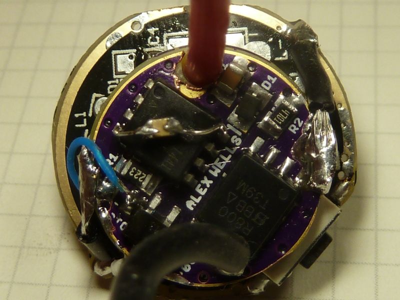
hers' an example showing the extea 0.1 uF cap wired (pic came out dark, sorry):
Thanks to you all for constantly fine tuning these drivers. Comfychair, welcome back!
.
As it is talked about re-moving (or adding) C1 behind the diode, I’d like to add some thoughts. Following some recent discussion I came to the conclusion that this might not all be common ground:
- The value of C1 - if behind the diode - influences OTC timing and the values needed for the CapThreshold in the firmware
- The stock value for C1 is/was not 10y, but 4.7y on a Nanjg105c(8x) and 2.2y on an AK47a(3x)
- Even the good X7R 1y OTC variates within the 20% spec and I measure between 0.83y and 1.07y
Note: All said is experience with linear driver (7135 only) where LVP is behind the diode and dual OTC threshold (3 timeframes) used.
When I started selfbuilding (linear) driver I used 10y for C1 as everyone else did, in the same time I used the AK47a as a single sided driver with added OTC. The OTC timing was greatly different (and I had to use firmware-values over 250 in some cases).
Then I started measuring the C1 stock values, as they were probably the basis for JohnnyC’s Star firmware. Of about 15 105c and Qlites I salvaged in 2014 all had a 4.7y C1 (may change or have changed with time and supplier). The AK47a on the other hand had a 0603 2.2y C1 - and I used some 10y. Results varied greatly.
So the value of C1 behind the diode does seem to influence the OTC timing.
The 20% production variance of the OTC influences the timing as well, but not as strong.
My conclusion was to bin C1 and OTC. I use C1 only in the range of 4.32y - 4.52 y and OTC in the range of 0.87y - 0.93y (greatest yield after binning…) and adapted my firmware to the middle values. I get very consistent OTC timing for dual threshold ever since.
This led me to the conclusion that the variance in the 1.1V voltage reference of the ATtiny13a a is negligible (a member had stated so somewhere).
I never followed the change to bypass the diode for LVP (R1 on Bat+) as this seemed to influence OTC timing as well. I had no intention to open that can of worms.
I just wanted to bring to notice, that if you re-introduce a cap behind the diode for FET-related reasons, that this might mix up OTC timing again as well. Especially if inconsistent values for C1 are used.
I never seen 'y' used for µF. Is this intentional?
For the example above in post #347, and I think for all my uses, using the 0.1 µF cap is for e-switch lights only, so these don't have a need for OTC (thank goodness!). Timing is rock solid, dead-on in the 85's for e-switch use, and long clicks are with the MCU running, so very different, much much better for the user experience.
It's a good point you are making though, since the vast majority are still modding clicky lights, and I and others see timing issues with the long clicks for OTC.
I had not heard about 4.7 µF caps used in 105c's and Qlites. Maybe the 10 µF was measured earlier than 2014? It's easy to measure a cap - I've done it several times, but don't recall someone actually measuring the values.
I have no idea where the 10µ come from. I even had bought 10µ for the first driver I wanted to build, as C1 was stated as 10µ everywhere. Then I ran into OTC timing problems and measured the C1 from disassembled Nanjg boards as 4.7µ and 2.2µ. Not on the board, but the single dissoldered capacitor. I bought my last Nanjg and Qlite in 2014. I’m sure that the chinese will use any capacitor that is handy at the time, so they might be different earlier, or today, or with the 105d. The main point is not the value itself, but that C1 seems to interfere with the OTC timing, if on the MCU side of D1.
oops, old habit. quick and dirty way on a keyboard that does not have a µ.
I just confirmed the cap myself. I had a 105c missing an MCU because I needed the 13A at the time. It's a 105C 6x7135 bought from FastTech probably in 2014 as well - should be this one: https://www.fasttech.com/products/0/10001683/1122301-6-amc7135-4-group-25-modes-led-flashlight-driver-c.
So, I melted some solder on the iron tip, applied it to the side of the cap while holding the cap with a tweezers, and it came right off, quick and easy. Now that it's off the board, measured it on my old Fluke DMM, and it showed 4.6 µF, which is typical - the readings I get are always lower than the rating, so probably a 4.7 µF.
This is really interesting... Think'n further back, maybe the 10 µF value was more common... comfy or maybe RMM might know more?
Unfortunately I realized after setting this up that it’s a pretty terrible setup, so these scope images are somewhat worthless. My test LED was an old XP-G, probably with some damage, which only pulled around 2.5A from a high-drain cell. That said, they aren’t entirely worthless so see below. Scope probes are placed with (1) on FET gate, (2) clipped through the center via onto the BAT+ pad, and (3) clipped onto C1 right next to MCU VCC. I’ve got about 60mm total of 26AWG LED wiring and about 600mm of 18AWG battery wiring. I need to swap the LED out for something which will pull more current and use a bit heavier LED wiring.
The build here is using a v030 PCB with these parts:
- C1 - 1uF (X7R - #C2012X7R1E105K125AB)
- OTC - n/a
R1- 19.1kR2- 4.7k- R3 - bypassed (0-ohm)
- R4 - n/a
- R5 - n/a
- R6 - n/a
- D1 - stolen from Nanjg (~0.2v drop)
- Z1 - 4.3v SOD-123 Zener w/ legs bent to fit on SOD-323 pads (#MMSZ5229B)
- MCU: ATTINY13A-SSU
- FET: PSMN3R0-30YLD


Thinking of getting some V030 boards and building a few with ATTiny25 MCU’s, shall I? Tired of the issues I’m seeing on my triples and quads.
I think they are functional enough for an advanced builder like you to make something out of them. As I mentioned above, my first test was a crappy one!
Definitely don’t forget that you’ll need SOD-323 and 0603 components. For the build above I populated R1/R2 with 0805 size and it was beyond “tight”: one had to lie down on it’s side. The SOD-123 w/ bent pins was also a very poor fit and very close to the resistor pad next to it. (The 0805 on C1 was no problem though, even w/ the Pomona clip.) You might want to make yourself a note about R1/R2 being reversed in case you forget before they come in (sorry about that, I’ll correct it in the next revision).
I wouldn’t be surprised if a limiting resistor was needed for the Zener. If we use a 5.1v Zener maybe something in the range of 10 to 50 ohms would be good? We’ll know more after I do a higher current test.
You know the drill… no guarantees… you’re the official test pilot! ![]()
![]()
![]()
Uh… I was given the 10uF number by someone who claimed that checking capacitor with a multimeter wasn’t accurate enough, and that he had measured the 105C part properly with whatever super-technical lab grade stuff and that it was a 10uF. Not saying any of that is fact, just that that’s where the number came from. I’m pretty sure I remember who it was but haven’t gone looking for the exact post, so I don’t want to name names.
Ordered. And to get a solder paste mask? Where do I get the layers Zip file?
I probably wouldn’t sweat it at this point.
I just double checked. The tcream layer in the zip from OSH Park is correct.
Ordered stencils as well, time to double check parts inventory… ![]()
comfy - no sweat really, like wight said. Just interesting in pt of history - could be they used 10 uF caps early on. 10 uF caps are so well proven, I’d feel it would be risky to experiment with lower values, unless it’s a major re-design as wight is doing, of course.
Just fyi, I’ve measured 10’s, 1’s, and 0.1’s uF caps with 2 different DMM’s (Fluke and advanced model UNI-T) and they all measure slightly lower, but pretty consistent in the range, clearly identifiable.
I had no intention to point a finger at someone and I always saw it as minor details - which it probably still is.
The reason I brought it up now and here is that you all thankfully invest a lot of time and effort and I wanted to avoid that you - unknowingly - might use different components and have strange results, be it at the FET, at the OTC or while adapting firmware. I can’t help otherwise with these drivers but I follow with interest.
Alex - didn't look carefully at your v030 til now. Wow, impressive all that fits! Ohhh - is that a MCU pin #3 pad connected, but covered up? I'm really not lik'n soldering a thin wire to pin #3 directly on the v009's for a locator /LVP LED. Looks like I could just scrape off the covering of the pad?
Edit: Debating whether I should order these 030's now or wait til some testing is done. Not sure I followed everything, but have you been able to breadboard/proto/test this out somehow?
See post #352 above.