Ok, I’m looking at the component list for this driver and seeing that Alex built one with the ATTiny13A to start with and bypassed the Zener Resistor (200 ohm) . What UI then was used?
And this makes me wonder WHY the 13 components instead of 7? I’ve built a LOT of these with zero issues, so what are we trying to fix if staying with the 13A and normal A6 firmware? If all this is to make it work with the lighted tail cap, leaving that out is far easier!
Even a factory ATTiny25 driver with Bistro runs my Quad Cu X5 with ease, making right at 3000 lumens on the little 14500. I had the tail cap down to a 0.14mA draw with 2 LED’s and a 12K resistor, but removed that this afternoon.
So I’m trying to figure out what firmware to flash, which MCU to use, and just why all the xtra components…. Has R5 been established? Is 1uF still good for the OTC? ATTiny25 and the latest Bistro? Got parts in hand, ready to go, need to know where before I start driving.
In theory, any firmware should work. I don’t think anyone has actually done it yet though, so I wouldn’t expect the best results without a few trial and error steps in the middle.
It doesn’t have to be bistro, but if you go with tiny25 there aren’t a lot of other compatible options yet.
I don’t even use bistro on lights I build for myself. It’s like those big cafeterias you go to when the whole extended family is together and you need dinner but nobody can agree on anything. It has enough variety that everyone can eat something, but none of it is as good as what you’d get at a more specialized restaurant.
What if one used a capacitor between the FET gate and ground? That would smooth out the signal to turn the FET on, which would reduce transient spikes and make the FET operate in linear mode at least some of the time, absorbing some of the energy that is going to the battery and the LED now. The LED and battery would heat up less and operate more efficiently with a more nearly constant current. It would not effect turbo mode.
In the BLF A6, for instance, LED heating in the higher PWM modes is quite significant because of the small head. I am not sure how much it would help the battery but it would certainly be better for it.
The FET needs to be switched hard and fast, doing otherwise is generally frowned upon. Generates massive heat. FETs are great when used as switches, pretty terrible if you try to use them as variable resistors. 'Smoothing out the gate signal' is the last thing you should try to do.
A gate resistor does what you're speculating about adding a capacitor (a capacitor won't have that effect), and it also slows the FET's switching time, leaving it in that not really on but not really off bad zone. If it can be made to work without a gate resistor the FET will have a much easier life.
Put a choke (inductor) inline with the LED to soften the square wave and cut the output on lower PWM timings way down. Leave the FET switching as-is. Problem is fitting a large enough inductor on the driver (and adding the choke requires a large flyback diode as well). This was already done on the 1st-gen BLF-SRK boards. Between 0.8 and 1.2uH, with a rating of 12-15A, works well. Higher uH gives greater reduction at small pulse widths. Inductors with those specs are rather large, fine for giant drivers, not fine for 17 or 20mm.
I think I read something about that a few months ago in some obscure GB thread
But for what it’s worth, I’ve done some experimenting recently and found it’s possible to get beautiful, PWM-free low modes from the FET by giving the gate a small charge from the pull-up resistor (about 150-250 cycles @ 4.8MHz on the attiny13a). It can then be left floating for a while.
The nice thing is that it makes a nice linear looking ramp, probably because the FET has exponential response to gate voltage. It will also go as low as you want it too, with the led barely visible in a dark room. The ugly part is that the charge time needed changes significantly with voltage and probably also from part to part and with temperature. So this will be difficult to use without some sort of feedback loop but I’ve not given up on it yet.
That’s the same thing I discovered, and I wasn’t able to do much about it in software. It seems led4power ran into the same issue, and used a separate power channel for the lowest modes. The FET is incredibly unstable at the low end.
Up front: Sorry if I miss anything folks - I don’t have a lot of time so I’ve skimmed the last 10+ posts.
I used the ATtiny13A for a couple of reasons: (a) because I’m rusty and I wanted something I knew I could program properly. (b) I also knew that it would be stable regardless of the hardware, so I’d be able to move through the modes properly and view them on my oscilloscope.
Having done those things, it looks to me as if this driver is ready to use with the more sensitive ATtiny25/45/85 MCUs. The extra components are present for a variety of reasons - one resistor is for the tailcap LEDs, one is for OTC pulldown, one is an FET gate pulldown resistor, and then I think the rest are there for regulating the voltage to the ATtiny25/45/85 (spike reduction). For more details look at #’s 301, 314, 326. I’m sure there are more details in there somewhere. (I’m under the weather today and my mind is elsewhere to boot. Sorry!!)
R5 hasn’t been established, but Sharpie made a suggestion a few posts ago. I left the OTC pad at 0805 with the intention of testing moving to 10uF w/ a pulldown. Sharpie suggested 100K. His suggestion was also to change R1/R2 out for 10x the resistance, which I find to be a very reasonable suggestion. (so approximately 191k / 47k) Rather than bypassing R3, 10ohm might be a good start. Sharpie seemed to think so too. I still haven’t ordered 0603 sized components, but once I do I’ll test that myself.
Looks like you and comfy may be onto something with that SiR404DP. Good work.
[quote=fixed it]
Unfortunately I think you’re exactly right. In order to avoid a large increase in component count it may be possible to use a current sense resistor and measure it with ATtiny25/45/85 using the 20x gain setting. The ATtiny13A doesn’t have this 20x gain setting and would be unsuitable. I assume that an RC circuit would be used to maintain the voltage on the gate pin.
Yeah, I can build a UI I’ll be happy with within those restrictions but it won’t be something most people will like.
Would people bypassing springs and trying to find FETs with slightly lower resistance accept a current sense resistor? I really don’t know. Haven’t worked out the values needed either as it’s not something I can easily do in any case.
What I might try, as it’s a simple change, is to connect the LED negative to an ADC input and try keeping a stable LED Vf. I’m thinking I could self-calibrate it with the 7135.
As for voltage on the gate, that would be easiest indeed as you could use built-in PWM. Or you could do it with just a large enough resistor to ground, using the gate’s capacitance and the internal pull-up resistor of the MCU. Somewhat harder to program though. It can even be done with none of that by fully draining and recharging the gate every time a change is needed (what I did in my testing). It takes about 50 µs so it should not be noticeable.
Read this piece of ancient history. Feel free to laugh.
It does work, I've built the circuit with a 10K pot (higher would be better, since it's wired direct between B+ and B-) as texaspyro describes there. The FET does get uncomfortably hot in the upper half of the range, like between 70-98%. At WOT it stays cool.
I did come across that thread when searching for previous similar attempts. And no, I did not laugh. I actually tried something similar with good old transistors about 10 years ago, trying to put a touch sensitive switch on a project. But I’m getting off topic now so I’ll spare you the details of that failure.
My first build failed. Nada, nothing, zip. I have a short across a couple of components due to not having proper sized smaller parts. Will punt later. Today has been a grandpa day, 1st time for everything I suppose. They don’t know it yet, but I sprinkled some small resistors and XP-E2 emitters in the diaper bad, see if anything grows there…
Though I admit that I am week at circuit level electronics, this isn’t an FET from a typical budget flashlight that overheats if you take its series resistor out. It is bigger than the LED and, properly cooled, it should be able to absorb a comparable amount of power. I didn’t get this out of the blue. I don’t remember which thread but the EE who suggested a gate resistor said it could absorb power. If the gate resistance of the FET is high enough, then probably a gate resistor is better, using the FET’s gate capacitance.
I have tested it with the big beefy TO-252 Vishay 70N02 and it gets hot enough to burn you. FET hasn't died yet, but what kind of a reduction in lifespan would be acceptable to you, to get something that can be had by other means that doesn't cause components to fail?
I’m real happy with using PWM level of 2 on the single 7135 of a FET+1 driver. I can now set the moon mode PWM value via the UI from 1 to 7 in my latest Narsil version, and 2 has been working well so far, even on a low cell. It’s soo nice now to set the PWM level of moon via clicks to see the differences easily, in the the light.
Nice. I always end up having to add a bunch of moon modes then test them in a light box to figure out which one works best, then remove all but that one. I can get it reasonably close just by shining it next to a reference light, but the light box is still necessary to make the final choice.
A value of 3 seems the best for the lowest, stable value for a 350 mA 7135 and that’s what I’ve been using lately, and I’ve found you have to raise to maybe 5 for a 380 mA 7135, so I’ve been using 350’s now exclusively. What value to use for moon mode has been bugging me for a long time, so best to make it configurable, just wish it was easier in the UI to adjust. Right now it’s in the configuration settings, but would love to be able to tweak it while in moon mode. Sometimes I like it super low (2), other times 3, or higher at 6 or 7 is nice to have. Should treat moon mode as a separate state with it’s own button actions.
My configuration settings are now stored in 3 bytes to cover the 10 different setting values.
It also depends on the exact 7135 chip and the emitter, and even how many. Some 350mA chips work better at PWM=2, others work better at PWM=3, and the 32x7135 SRK driver lights up even at fast PWM=0. Older emitters require a higher PWM level than newer ones, usually. The highest I’ve seen was an old XM-L which needed PWM=9.
If I have an e-switch I don’t bother with specific modes. I just use a smooth ramp from moon to maximum. On a single-channel driver (or tiny25/45/85 FET+1 with a slightly different pin setup), the low end can have extra-fine adjustment by using PWM+PFM, so you can get lots of precision in the moon range instead of just a couple levels. I haven’t actually seen a driver set up with two channels on independent PWM counters though, and now I kind of want one.
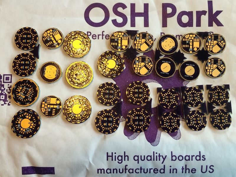
Some happiness arrived in the mail yesterday. Those 0805 SMD pads look soooo tiny.
I’m ok with learning to reflow the one sided boards but how do you reflow a two sided board and not lose all the parts off of the other side?
Is it time to add a hot pencil to my soldering station ?
Surface tension of the solder is greater than gravity. They stay floating in place on their pads just fine. Unless you bump it while the solder is still liquid. A big heavy part with small pads can sometimes fall off, but that's why you do the side with heavy parts last (or hand-solder them afterwards).