Thanks All! Notice the brightness of those LEDs? Wayy too low resistance used. On the UF-T18 there was a resistor already mounted on the switch PCB, but must be low. Probably only used for blinking in stock driver - looks ok when blinked, super bright when on steady.
Actually the UF-T18's switch LED is the ultimate low moon mode. It actually throws a pretty good amt of light ().
Ok - I’m calling the physical SMD LED wired to pin #3 the “Indicator LED”, but the “locator LED” is the functionality of it being ON when the main LED is OFF. Thought this might be confusing, so no prob, ask away.
I took only a brief look at PID before deciding on something simpler. The atmel example code I found for it compiled to like 5500 bytes and the MCU only had 2048, so I put it aside and tried to come up with something tiny instead. However, I hear PID can be implemented in far less space than what I found…
wight linked to one that was supposed to compile in 534 bytes. I’ll start there. Space is certainly an issue, I don’t know how much I will be able to afford. My “development” firmware is getting full, but some of that stuff can be stripped out for “user” firmware.
I was just looking at Mountain Electronics and I saw that the DRJones H17F driver with lucidrv2 uses PID. And from reading about his UI, it seems fairly rich as well. That driver is using ATtiny25.
Yeah, I’m sure he has spent loads of time on his drivers. I was only remarking that PID is definitely possible in a small(ish) space. Hoping to encourage some of these talented people working on drivers and firmware, confirming that it can be done. It wasn’t long ago that TK didn’t know it could be.
Doc Jones is famous for getting the most of every single bit in every single byte. He’s probably got the world’s most efficient PID algorithm in terms of memory usage. Also, 2KB code space in a 25 is a nice bump… I’m amazed what he’s done is so little space of the 13A’s.
Is it the time it take the heat to get from the LED to the sensor that you are compensating for?
The LED won’t get any hotter after you reduce the current.
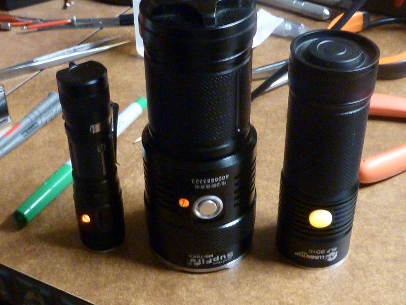
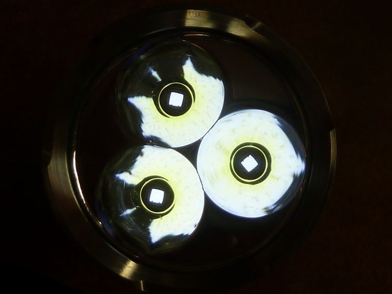
Just modded my SupFire M6 to add the indicator LED and light pipe, then upgraded the 85 to the latest Narsil. I used this light pipe: mouser-LPCM050CTP, only $0.56 each. Came out nice! The 3 LED's will work on a PWM setting of 2 for moon mode, and I measured a true 0.1 lumens on fresh SAM 30Q BT's. On hi, measured lumens: 5202 @start, 4991 @30 secs. It's got U3 2A XM-L2's on 20 mm Noctigons, 20 AWG wires.
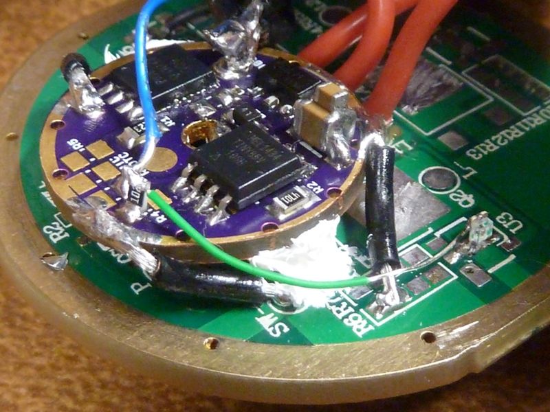
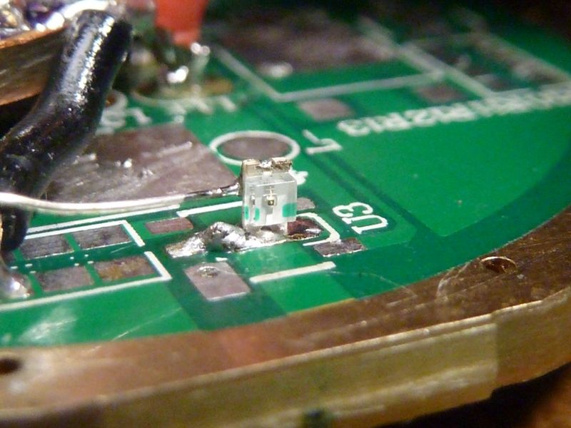
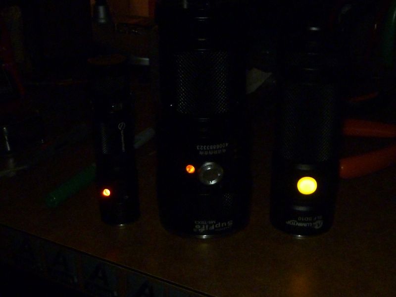
I think the brightness of the indicator came out really nice using a 1K resistor with an orange LED, mounted tombstone style on a ground pad, directly in front of the light pipe (had to align the old driver/contact board up). It's bright enough to see in a well lit room, but not too bright, and mounted next to the button makes it easy to find the button in the dark. Here's some pics:
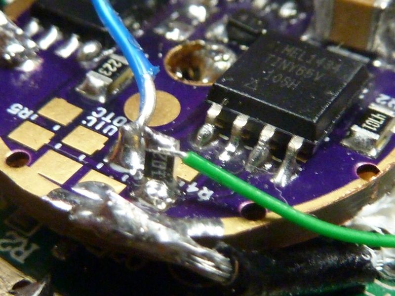
The 1K resistor, also tombstone style mounted on a pad from pin #3. The blue wire is for the switch (pin #2):
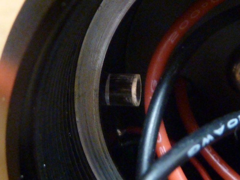
The light pipe is about 11mm long, while the M6 thickness is about 8 mm, but because I could set the LED position a bit back on the board, it matched up pretty well:
Err, it won’t? The LED’s temperature doesn’t simply “track” with input current. Think about it - this is just like an electric oven. Reducing the input current may or may not reduce the temperature - it depends on ambient temp, what’s around the oven, and whether you reduced the current from 100% to 80% or maybe 50% to 30%. Somewhere in there exists a “steady state” break point - above that point temperature will rise and below it temperature will fall.
For this application using lookup tables is tricky: they only fully function when they are created with knowledge of the many variables (LED, battery, light mass, external mass, ambient temp). Holding or not holding the flashlight makes a huge difference, but how do we know which lookup table to use (hand vs. no-hand) at any given time?
PID lets us dodge almost everything, I think. You brought up slow/laggy measurements - that may be an issue, I’m not really certain. My immediate take is that whether it’s an issue depends on your goal: I think most of us are ignoring the LED temp and are only interested in maintaining flashlight usability with very high power setups. (someone please let me know if I’m wrong!) In the case of maintaining usability, getting laggy temp measurements isn’t really a big deal - they’ll be reasonably close to “flashlight surface” temps and we should be able to tune the PID settings to achieve the right performance. To re-iterate - for me the “right” performance is a flashlight which I can continue to grip without burning myself, but also a flashlight that will not become scalding hot if I set it down on a table for 60s.
Very slick Tom E, good work. What type of wire are you using for your little hookup wires? The sheathing on the green wire which goes to the LED caught my eye as odd…
Soo, the tiny25/45/85 includes a useful extra feature which I should point out over here. They can measure vcc internally. No pin or voltage divider resistors needed. See my post here: Flashlight Firmware Repository - #790 by Halo
wight - that green wire is really old stuff I had laying around, not sure from where. It's maybe 3-4" with a large amt of the ends stripped - that's why a good amt is bare, it was partially used already. Guess'n it's bout 30 AWG single strand. Think'n it was wire wrap wire? Looks like this wire wrap pre-cut here.
Halo - that sounds interesting! I'm surprised the 1.1v ref would drop same as a direct batt readings, but I don't claim to understand these MCU's for sure.
:-/ Sorry, I didn’t follow that.
Your variable vcc is set as the reference then you measure the stable 1.1v. It’s backwards from how you normally set up measurements
Ahh, ok. Think I kind of/sort of understand. The 1.1v source is always a true 1.1v, but the reference source to read it is Vcc, used as the comparison for measuring 1.1v, so what you read will vary as the Vcc reference source varies. The resolution is less because you are reading 1.1v instead of a true batt+ level, I suppose, so almost 4X less resolution.
I’m actually still a little unclear on how this works Halo. Previously I suppose we were doing “single ended” measurements where we compared the voltage from our hardware voltage divider against a 1.1v bandgap. You’ve proposed measuring the 1.1v bandgap against Vcc (~4v for example).
I think I’m following you now Tom E. Are we thinking that 4v might yield a value of ~281/1023 and 3v might yield a value of ~375/1023? That doesn’t seem like a very large delta, but let’s stretch this out.
That actually looks much better. For our purposes we generally care about something like 4.2v through 2.8v I believe, so we’ve got about 134 measurement points in there. This is approximately double the resolution we normally have since we normally get 8-bit measurements ranging from the low hundreds to the high hundreds (120 through 190 or something like that).
 ).
).