Hello Scholars :GRADE:
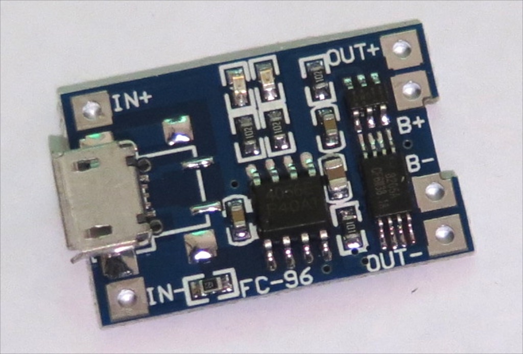
The original TP 4056 is only a charger, with over-charge protector. Here is the newer version of the TP4056, that has separate over-discharge protected output(that cut off if the voltages reaches below 2.4v). As you can see in the image, the inner B- & B+ are battery charging terminals and the outer terminals are the protected outputs.
So-
Have anyone experimented with these ones?
I am combining multiple TP4056 to create a 18650 cell pack. Purpose- Charging 6 cell 3.7v batterypack in less time.
Refer to this video that uses the original TP4056 https://www.youtube.com/watch?v=KoHtxZG7leQ
This video only explains about charging the multiple cells at a time. But I have selected the TP4056 ‘with protected output’, to make a permanent batterypack. For that I will have to use the output terminals on it.
But my main question is that, can I combine the output terminals of all 6 TP4056 together to get a single output? Will the protection work in that way?
Meh, it’s a 4056 clone, not the original tp4056 chip (which has a stylized TP logo). HKJ only tested the original tp4056 and I haven’t seen anyone chart the charge profile of any of the clones. Now no one seems to sell the originals anymore. They took a great thing and turned it into worthless junk imho. I had one clone chip that tried to dangerously overcharge and wasn’t cc/cv. Do not trust these things.
At least the Under-Voltage-protection works fine.
I have a self-built 1*18650 Powerbank with one of these and the thing shuts off at a good voltage (don’t remember is though)
And remember: These things don’t have polarity protection. Once you put in a cell the wrong way, the chip is dead.
Only way to know is to test.your next batch from the same seller may be completely different though.btw the ones I get from ic station work perfectly.and have across 4 batches.
Hello Barkuti,
Mine arrived too. They are good. I checked two of them. They charge 2200mAh 18650 cell in or little more than 4 hours.
I got the 18650 spring loaded battery cases too. They go well with these modules. Just two-way-tabe it at the back of the case. .
I connected tp4056 protection board with one 18650 to some motor…it take about 6A. The board is dead in a moment. I tried another board…dead the same… not charging anymore, only heating, no output.
How this overcurrent disscharge works? I belive that is not working.
svicar1, 6A is a massive amount of current for one of these tiny 8205A FETs to handle, which may be the reason you are seeing magical smoke. :FACEPALM:
How are you connecting your stuff?
First, please make sure that is the maximum amount of current your motor needs to handle; if it is higher, then go with the higher number, better safe than sorry. :THUMBS-UP:
Now, please consider the fact that most battery protection boards with a single 8205A specify a maximum 2A of continuous operating current (the FET will drop ≈0,05V by itself at that current flow).
Thence, if I were to be called upon for advice on an application like yours (max 6A?), I'd recommend to make use of no less than 5 of these boards. Battery cathode connected to each B- pin with a short, equal and not overly thin sized lead/wire. Likewise, load negative pole should be symmetrically connected to each OUT- through equal sized leads/wires.
With regards to charging the battery, just connect its anode to the amount of boards you plan on using for charging. If you are fine with ≈1,7A, connect the battery anode to just a couple of boards, the same ones getting the 5V input for charging.
helo
I will tell you exactely what I need
I have hand vacuum cleaner. https://cache.osta.ee/iv2/auctions/1_1_8495647.jpg
Originaly it has 3x1.2AA bateries in series. All the time charging it kiled batteries.
I take off the “charger” (few resistors, diode,…)
I decided to put inside only two 18650 (from old laptop) in paralel. And manualy charge the cleaner when it will be necesarly.
Now I need charging (not a problem) and low voltage protection board…the booard tp4056 seem perfect…but there is a problem current.
The motor take 6A constant current and 14A pick current.
How to modify the tp4056 board in the output that will pass this current?
relay??
change FET?
aditional FET??
Or connect motor directly to battery and use out from boart to some buzer or warning led (that the bateries has low voltage and need to charge)?
As I said before, connect the battery pack cathode to all of the boards B- pin inputs, and the vacuum cleaner's motor to all of the OUT- pins, minimizing and balancing path resistance(s). When the boards are in operation under normal circumstances, their FETs are closed conducting electricity, and current flows between OUT- and B-. Since you say the thing can draw up to 14A, you may want to use 6+ boards in parallel to minimize the chances of a FET cascade opening, as each FET is controlled by its own “brain” (DW01 chip) and, with just 5 boards (5 × 3A peak current flow), we may find the protection kicking in from time to time if we often get near those 14A and our current paths aren't perfectly balanced (shouldn't be much of a problem, though).
Connect the battery pack anode to the boards B+/OUT+ (its the same thing) pins, so all of the DW01 monitoring chips are powered. Only the boards getting input power at their IN+ pins will charge the battery(es). Edited and fixed.
That's right, svicar1. Still, I warn you to use no less than 5 boards, 5 × 8205A FETs. At 14A peak current flow, no less than 3,5A will try to flow on each FET and it'll trip the protection…
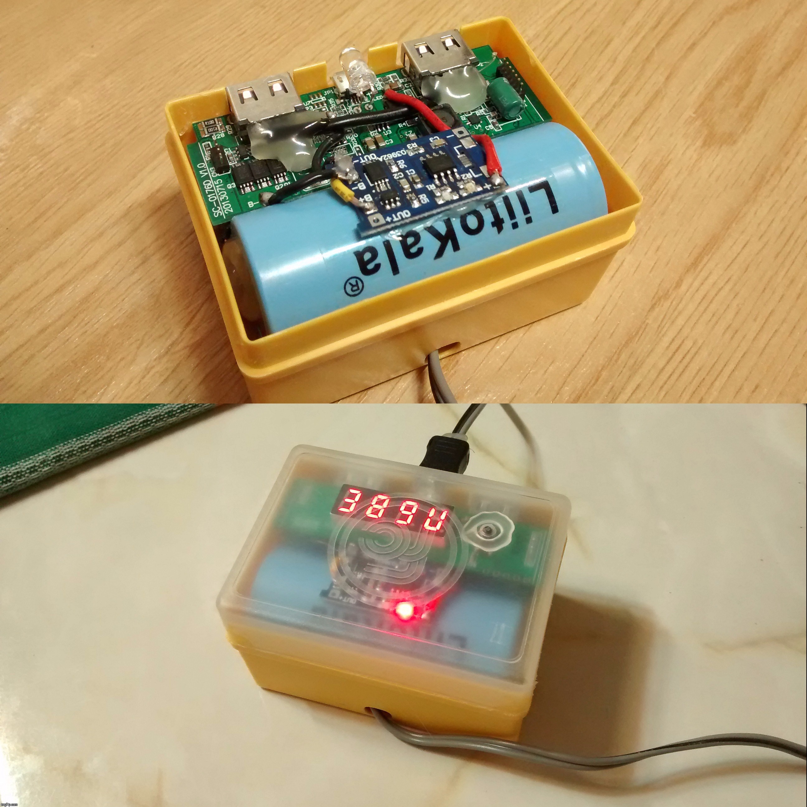
Also, you ought to know it is safe to use more than 1 charging board in parallel, even if your “charger” (PSU) isn't powerful enough (though don't blame me if you're using some sort of cheap knockoff). The boards just throttle themselves. Look at this pic:
Custom hand-crafted powerbank I made for a friend. That board uses a single TP4056 charging chip. After some analysis, I improved the charging engine with the addition of a TP4056 charging/protection board in parallel. His phone charger, a 1A unit, delivers up to 1,2A, but it hasn't burned out yet while feeding the powerbank (which now requests 1,7+A).
Cheers ^:)
P.S.: Relay? No, thanks. Those FETs do such a task very well already. Modern solid state relays are made with FETs. ;-)

