Would anyone know (or could measure) the inside and outside diameter of the gasket? The bottom of the gasket, part which rests against the washer.
Oh hell yea!! JDub that’s awesome! I need about a dozen of those translucent gaskets right now! I know its asking a lot, but if there’s any way Simon could make those available separately so we could update our existing lights that would be awesome.
I concur with djozz, by the way (as if he needs it). No need for the translucent washer in this light. In order to use one of the “traditional” lighted boards that replaces the existing switch, you have to run the emitters really bright to get enough light through that little nylon ring. Replacing the washer with a washer board is much more efficient, and really the only way to do this light. Don’t trouble Simon with that since most of us are just going to take it out and toss it in the parts box anyway.
Just to add to the chorus: I see no need for a translucent/transparent washer. The design which replaces the washer with a PCB seems to be clearly situated as the better design right now, especially for this application.
… and if someone DID want a clear washer, they could easily find or make their own which was just as effective.
![]() Happy to help. Yeah improving the water resistance is a plan for the future. It’s not that bad now. This isn’t meant to be a dive light but certainly can be improved.
Happy to help. Yeah improving the water resistance is a plan for the future. It’s not that bad now. This isn’t meant to be a dive light but certainly can be improved.
Between PD pioneering this and the pictures you posted of the S2+ in all three colors with matching tails Simon is amazed at the work being done here and is happy to help his BLF friends.
As far as “asking a lot”…it’s really not.
Simon loves this project and seeing pictures of his S2+ lights enhanced like this made his day. ![]()
When I asked him to switch the black gasket to translucent I also asked if he would make extra for the people that had been pioneering this and he was happy to do so. He’s having extra translucent gaskets made. I’ll let you know when they are available here in this thread. I don’t know that these will be a store listed item but we’ll work that out.
Once they’re ready, 100 of them are coming my way. I’ll post here when I have them and I will help distribute to those who need them here in the US. These gaskets are on the house, compliments of Simon. I may send in small quantities to key people and maybe they can pay it forward so I don’t have to buy 100 stamps but either way…we got this. ![]()
Those gaskets sound awesome. I have made 2 blue ones for my wife to use in the house, they get less use because I have spoiled her with lighted ones. She will put a light down once the room lights are on and forgets where she placed them. She will turn the room lights of and look for the glow. Gotta love the quirks and tricks of tbi patients.
Interested in two translucent gaskets, but I’m in Europe. I could re-sent some for european members?
![]() I was actually hoping someone in Europe would chime in here. Let me talk to Simon and see if I can arrange to have some sent your way. Once I hear back from Simon I’ll send you a PM about the details. Thanks.
I was actually hoping someone in Europe would chime in here. Let me talk to Simon and see if I can arrange to have some sent your way. Once I hear back from Simon I’ll send you a PM about the details. Thanks. ![]()
That’s awesome JDub, I really appreciate it and I’m sure the rest do too! I’m happy to help with shipping. Also I should revise my “order” since I said a dozen (which I would have happily bought just to have extras) but I actually only have 7 of these hosts. So don’t send me a free dozen at the expense of supplying the rest of the crew when I don’t really need them.
How can I measure the bleeded current of my lights without a tailcap? Is this possible? thanks!
Hi!
Can anyone assist me figuring out the ‘best’ bleeder resistor value for BLF A6. The tail lights up nicely with stock driver, but the driver acts funky. I measured 0.24mA in the tail if that helps.
Thanks!
You mean how much current is bypassing the driver? I think it’s easier to just “do the math” based on voltage and resistance. To actually measure you’d have to isolate it somehow, or disable the mcu so it doesn’t turn on when you bridge the tail with a meter.
Maybe someone else knows how to predict it or something, but I use trial and error. Try a 680ohm first, and if that is still acting funny start going down from there. 680ohm, 560ohm, etc
Thanks for the quick reply.
I would if I could… but I just don’t have many SMD resistors laying around. I need to get me a value-pack ![]()
Higher resistance is better for efficiency when the light is on, but lower resistance is more likely to restore driver function.
Small update on the plan above - we have light! The host, LED, driver, and optic worked out perfectly. Unfortunately, I’ve ran into a couple of snags on the lit tailcap.
It turns out, the S2+ tailcap with rubber boot cannot be swapped out onto the S2+ with metal tailcap boot, the tailcap design is different. So, you can’t end up with a rubber tailcap S2+ in any other color except for black and gray (only two colors made with both rubber and metal tailcap). As such, I’ve decided the best way to go is to use the washer ring led on the red S2+ I have – a new project!!!
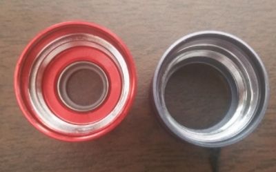
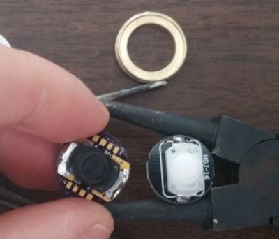
As for outfitting the gray S2+ rubber tailcap, it seems I should have gone with a 16mm LED board to match the original tail switch size as the 17mm PCB will not fit in the brass retaining ring, or is there another way?
Where would I place the bleed on a stock S2+?
I also built one with a rev 5.1 board with 1k ohm resisters in a triple xpl with a FET MTN-17DDm driver (without a bleeder), but the LEDs do not appear as bright as the ones shown in this thread.
You probably don’t need one
I tried without a bleeder but the tail cap nor the light will turn on.
I’ve built a bunch of S2+ lights but I’ve never bought one already working, so I’m not sure what driver comes in that light. But if its got 7135s on the bottom of the driver near the positive spring, just drop a resistor between that positive spring and the center pin on a 7135 (they’re all connected to ground). Just be careful not to short anything.
Here’s a photo of one I did:
