![]() I was actually hoping someone in Europe would chime in here. Let me talk to Simon and see if I can arrange to have some sent your way. Once I hear back from Simon I’ll send you a PM about the details. Thanks.
I was actually hoping someone in Europe would chime in here. Let me talk to Simon and see if I can arrange to have some sent your way. Once I hear back from Simon I’ll send you a PM about the details. Thanks. ![]()
That’s awesome JDub, I really appreciate it and I’m sure the rest do too! I’m happy to help with shipping. Also I should revise my “order” since I said a dozen (which I would have happily bought just to have extras) but I actually only have 7 of these hosts. So don’t send me a free dozen at the expense of supplying the rest of the crew when I don’t really need them.
How can I measure the bleeded current of my lights without a tailcap? Is this possible? thanks!
Hi!
Can anyone assist me figuring out the ‘best’ bleeder resistor value for BLF A6. The tail lights up nicely with stock driver, but the driver acts funky. I measured 0.24mA in the tail if that helps.
Thanks!
You mean how much current is bypassing the driver? I think it’s easier to just “do the math” based on voltage and resistance. To actually measure you’d have to isolate it somehow, or disable the mcu so it doesn’t turn on when you bridge the tail with a meter.
Maybe someone else knows how to predict it or something, but I use trial and error. Try a 680ohm first, and if that is still acting funny start going down from there. 680ohm, 560ohm, etc
Thanks for the quick reply.
I would if I could… but I just don’t have many SMD resistors laying around. I need to get me a value-pack ![]()
Higher resistance is better for efficiency when the light is on, but lower resistance is more likely to restore driver function.
Small update on the plan above - we have light! The host, LED, driver, and optic worked out perfectly. Unfortunately, I’ve ran into a couple of snags on the lit tailcap.
It turns out, the S2+ tailcap with rubber boot cannot be swapped out onto the S2+ with metal tailcap boot, the tailcap design is different. So, you can’t end up with a rubber tailcap S2+ in any other color except for black and gray (only two colors made with both rubber and metal tailcap). As such, I’ve decided the best way to go is to use the washer ring led on the red S2+ I have – a new project!!!
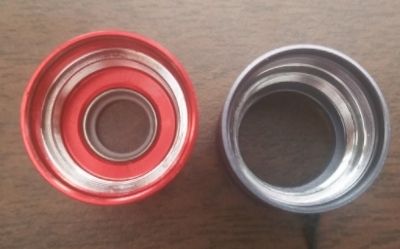
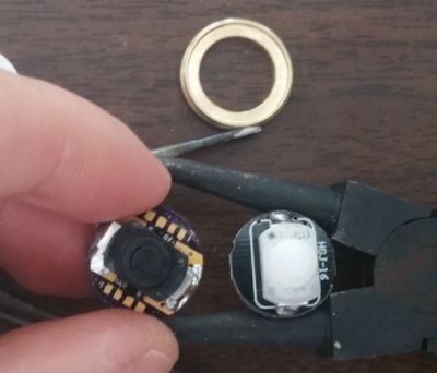
As for outfitting the gray S2+ rubber tailcap, it seems I should have gone with a 16mm LED board to match the original tail switch size as the 17mm PCB will not fit in the brass retaining ring, or is there another way?
Where would I place the bleed on a stock S2+?
I also built one with a rev 5.1 board with 1k ohm resisters in a triple xpl with a FET MTN-17DDm driver (without a bleeder), but the LEDs do not appear as bright as the ones shown in this thread.
You probably don’t need one
I tried without a bleeder but the tail cap nor the light will turn on.
I’ve built a bunch of S2+ lights but I’ve never bought one already working, so I’m not sure what driver comes in that light. But if its got 7135s on the bottom of the driver near the positive spring, just drop a resistor between that positive spring and the center pin on a 7135 (they’re all connected to ground). Just be careful not to short anything.
Here’s a photo of one I did:

Thanks PD! I think I will build a board without mcu to test it or maybe erase the mcu on a complete driver.
This may be helpful for those who don’t have the proper 2mm thick material around to make a clear washer. I discovered that the 3/4” washers with 5/16” holes are exactly what is used in tattoo machines, here are some on eBay in clear acrylic . They also come in frosted clear acrylic and various other colors :).
will it be available separately, that we can update existing hosts?
![]() thanks
thanks
I spent a couple hours playing with different LEDs and resistor values with very little success, basically, if you try to use different LED colors with much different Vf then the light output will vary significantly between them over the operating range of 3.7-4.2V. No combination of resistors for blue and red LEDs produced a consistent light output from each LED. Best results are obtained by using all LEDs of the same color (really more same Vf = forward voltage) IME YMMV.
If I had the Rev3 PCB and I want to use the Rev5b LED ring…where on the Rev3 PCB should I connect the positive and negative leads from the Rev5b LED ring?
I feel really stupid asking this question. ![]()