Nice, I was sure someone will made one with those great emitters !
Triple emitter for me too, on my SRmini II :


Stock emitters on the left, 4C on the right.
Nice, I was sure someone will made one with those great emitters !
Triple emitter for me too, on my SRmini II :
Stock emitters on the left, 4C on the right.
I fitted a BLF D80 with an MTN-17DDm driver running Bistro UI, using no additional parts.
The original driver PCB is 19mm, so the new 17mm PCB wouldn’t sit nicely on the driver shelf.
I drilled out the retaining ring slightly to allow room for the driver’s components and soldered the driver to the cell’s side.
The result ain’t pretty, but no one can tell while the light is running!


Moving the driver means less space for a cell. A 65mm flat-top HG2 cell now extends 3mm past the tail end of a “long” D80 tube. This setup works fine, but a “short” tube or protected cell will not.

With Bistro UI (my favorite!) and no more PWM, this D80 will get lots more use now!
I have a stack of drivers taken out of Lucky Sun D80 lights. Every single one is 17mm. I don’t understand your 19mm dilemma. I was on the testing team on those BLF Special Edition D80’s, every sample, every light I bought, all 17mm drivers.
Hmm…
I just pulled my other D80 apart. Head and driver dimensions are the same as the one I modded. I received both lights mid-March.

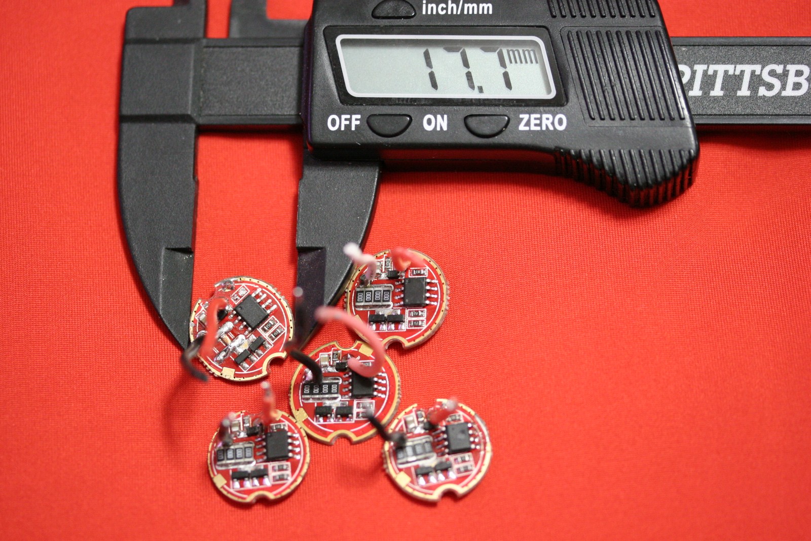
And just to show I’m not “cheating” with the calipers… ![]()

The diameter above the shelf is ~19.50mm, and below it ~16.75mm.
Would you like a 19mm driver to add to your stack? I’ll ship it free! ![]()
Amazing. I don’t know why I’m suprised, they changed stuff on Krono for a year before they finally shipped the BLF SE light. But geesh, a jump from a 17mm driver to a 19mm is a big deal! I double checked mine after I said that just to make sure I wasn’t remembering wrong (I have a knack for that) but I’ve got A17DD-S08 drivers in several and an LD-2 in one. All 17’s. And the stack I have in my kit, all 17’s. Blows me away.
Edit: Ok, pull the spring off that driver, put a bit of a solder blob on it, should work……
Send me the 20mm driver and I’ll piggyback an FET driver inside it, you’ll be able to put it right back inside same as before and it’ll look stock, but perform much better. ![]()
I can even put that particular driver inside, or build you a new FET+1 with Bistro.
What would have prompted such a change? Seems like more work and more copper!
Does my 19mm driver look like yours with a wider margin added around the edge?
I should clarify, I already planned on running HG2 cells in this light. They fit fine with the “long” tube and driver spring in place.
I only mentioned the length issue as a caveat to others who may attempt my “bass-ackwards” driver configuration. :laughing:
19 mm here as well, but did not have any issues fitting 17 mm drivers.
Also managed to get rid of the beam rings and get decent focus (but not centering), on the one refitted with an XP-L Hi. Used a 0.9 mm gasket meant for an XM emitter with a 7 mm aperture reflector. (Think these are the ones: https://www.fasttech.com/products/1616/10001923/1581402 )


Geesh! That defined hot spot is what I LOVE about the D80! Nice shot!
Unreal. I have 5 drivers here that are still completely intact (I rob resistors and brass buttons and stuff then throw em away) only 2 of these 5 are of similar size.
1 is 16.9mm
1 is 17.5mm
1 is 17.7mm
1 is 17.8mm
1 is 18.8mm and this one I absolutely know is from a newer BLF SE because I marked it when I took it out of blueb8llz light.
I never paid attention to that before! Crazy.
Notice the calipers…
I’m thinking that Dale, DEL, and I have BLF D80s with slightly different dimensions in the heads.
Both of my samples from mid-March look like this:

17mm driver - 16.75mm width under shelf = 0.25mm total overlap
Divide 0.25mm by two, and a 17mm driver would have a ring of 0.125mm overlap with the shelf in my lights.

Finally everything is inside, the torch works and it pulls 2.6 Amperes ![]()
Funny little thing burns a hole into the night…
I use a steel pair in the workshop, but keep one of these at my desk.
So much safer to measure lithium cells with :laughing:
To be honest my replacement drivers overlap the shelf my very little, but I do not see them falling in. For electrical contact, the overlap with the retaining ring is important, and that is more generous.
Uh oh, I’m busted! :laughing:
To my credit, I had enough forethought to NOT measure the HG2’s length with them! ![]()
I’ll get a set with plastic jaws for my electronics toolkit. Thank you both for the safety reminder.
I was afraid that with such little overlap, the pressure from the cell might punch the driver into the recess under the shelf.
I will try your method with the other D80 and another 17mm driver and report back.

Spent a solid day doing some small stuff with the bulk focused on a D01 mod. Reinforced positive contact ring, bypassed springs and traces, mounted a FET driver onto the stock driver, sanded the copper heatsink and the maxtoch mcpcb to 1500. All that is left is to solder the leads to the mcpcb and the switch wires to the driver.
Speaking of switch wires… Is there a particular orientation to connect them to the sides of the OTC on the FET driver or does it not matter?
Great video, X3, I enjoyed that very much!
You could do with a simple led-tester, saves you some time ![]() I use this one, it even works with 3 leds in series because it is powered by a 9V alkaline. It comes with small alligator clips that are very handy, I just swapped the momentary switch for a small clicky switch to be able to use both hands.
I use this one, it even works with 3 leds in series because it is powered by a 9V alkaline. It comes with small alligator clips that are very handy, I just swapped the momentary switch for a small clicky switch to be able to use both hands.
Thank you for the kind word, I saw the tester in one of your videos and it seems prctical.
I was too confident in my skills so I waste some time but eh, that’s how you learn things !
The second time I checked them with my DMM, one by one and everything was ok.
I guess one solder joint was not good because orientation were the same before/after…
