OK thanks again for your support, some significant progress and a further question after following your suggestions and insights.
There is good continuity between the head retaining ring and the sliver of driver track that protrudes from underneath the ring, both with and without a paperclip. So that part is fine.
I then reassambled the light (I have periodically done this) and was able to momentarily get quite a bright light (blinded me) output. It was intermittent, sensitive to physical movement and tapping of the light, and turned off most of the time. This would suggest to me the possibility that there’s a dodgy solder somewhere…
So next step is what you suggested - checking the other side of the driver. I’m just not 100% sure about how hard to pry it out - do I pry it out from the light/star side, or from the spring side (from the light/star side, there is a metal plate below the light board which doesn’t look very movable)? With the retainer ring removed on the spring side, the driver appears to be “stuck” in place (possibly with some adhesive?) and won’t budge easily with some exploratory tweezer work. Do I need to melt something or just pry it out by inserting something sharp into one of the two slight indents between the silver ring and gold ring:
Thanks, I did see that in the instructions, but even now with some “play” in those wires, the driver seems fairly stuck - to confirm, it should (once LED wires desoldered), come out through the back of the head unit or the front?
The driver should not be glued. It is typically just the perforation remains, from where the PCB was attached to the bigger sheet of driver boards, that makes it a tight fit.
You need some kind of sharp pick to gently pry/hook/pull on the the two flat edges. You can also use something like a toothpick to push from the other side, through the LED wire holes, at the risk of damaging some components on the PCB.
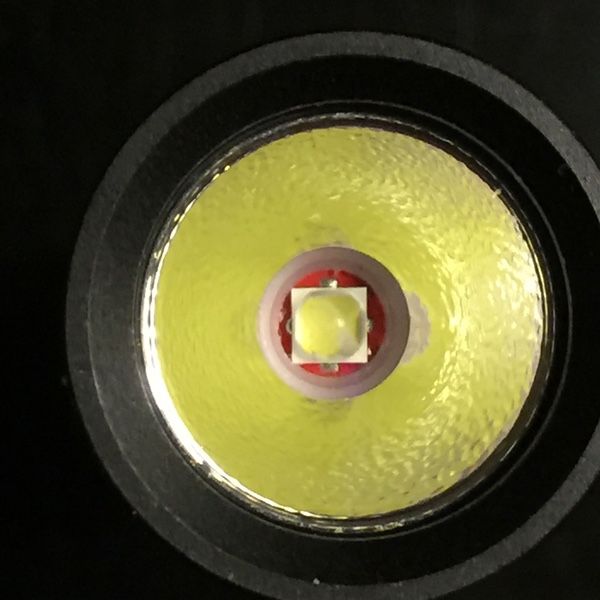
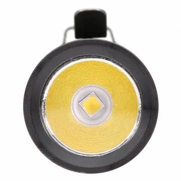
Just to clarify, the led is soldered to the red metal core printed circuit board(mcpcb) and the driver pcb which you only see from the spring side has all of the control chips on it. Use a tooth pick rather than anything metal and just push it through one if the led wire holes to push the driver out of its seat. It’s just a press fit. The retaining ring pressing on the driver is what grounds the driver to the bare metal of the seat it rests in allowing current to flow between battery , the switch, the tube, the head, and the driver which controls current on the side of the led. Battery + feeds both the driver and the led so you should have continuity between the spring and led. Sometimes one of the solder bumps on the led mcpcb is too tall and shorts to the reflector. If that happens on the led- bump the driver is bypassed and you get single mode Direct Drive. If it happens on the led side you get no light and possibly an overheated spring(loses temper and spring compression) which looks darkened. Even if you fix the short the spring has lost it’s temper and generally doesn’t maintain battery contact well leading to intermittent operation. If the springs look good then chances are at this point that is an issue with the driver, either poor soldering or a bad component. When you pull the driver inspect the wires where they pass through the holes for any cuts as sometimes the mcpcb will twist as the bezel is tightened and the insulation gets cut.
More specifically in a 15 amp Convoy S2 triple with all springs bypassed, 30Q battery, copper heatsink soldered onto pill, and MCPCB soldered onto heatsink, strobe mode only works sometimes. Not most of the time.
It strobes a few times, then either goes into moonlight mode, or shuts off completely. Sometimes it strobes only 2-3 blinks, then does this behavior.
I had built the light originally with the driver in the Kronos X6, and it also acted weird. With a 30Q, turbo mode only lasted a very short split-second, and strobe mode was non-functional. When I used an NCR18650B, it behaved normally and everything functioned fine. It seems like it has something to do with the amp draw, but I’m no expert.
Thanks - I’ve desoldered the led but can’t for the life of me get the driver to pop out of its seat (have removed the driver retaining ring). I’ve tried multiple toothpicks, tried hammering on the toothpick, they just break after a lot of force is applied. Have tried picking at the driver from those two slots with tweezers, but it won’t budge. Tried running the soldering iron around the outside of the driver to “loosen” any imaginary adhesive or solder there but no luck.
Have even tried (bad probably) pulling on the driver spring with pliers but no luck!
I feel your pain. Modding isn’t always straight forward and often ends with more damage than you started with. I haven’t seen one quite as stuck as yours but statistically somebody had to draw the short straw. Under normal circumstances solder won’t adhere to aluminum and I haven’t heard of them using glue but stranger things have happened. It sounds like removing the driver might require enough force to damage it so you should probably have a spare ready.
Yes, unfortunately a significantly amount of the time modding is spent repairing stuff you scr#wed up. And in my case searching for small parts that I dropped or just left at bizarre unlikely locations.
They changed the plastic centering ring too, the new one is actually better, it will less likely twist the dome off the led when the flashlight head is being removed.
Anyone know where to get the new ones? I’ve done enough accidental de-doming for now.
Yeah, I know, if it’s working why try taking it apart … well, just because.
Not sure this is the place for this qc issue… Just in case someone else has seen this.
I received a bare aluminum A6 two weeks ago and the head section is very slightly skewed. It is hard to notice, but i can feel it with my fingers. On one side there is a slightly wider gap between the head and the body and i can feel the head is not perfectly aligned with the body too.
The threads look fine - no cross threading, and the head screws in and out smoothly… I can’t really tell what’s wrong. It would seem the inner threads in the head have been done with a slight angle… No idea really.
I’m a bit disappointed of course, but i can live with it. I won’t go into playing customer service game with BG for that. Still… it is a surprising qc mishap for a BLF light… I don’t think i have ever seen a skewed part like that, even in the cheapest chinese lights i’v bought over the years.