Interesting. So, over-driving a 6V MT-G2 already resulted in early severe losses. Seems upgrading the inductor is the way to go from a performance/efficiency(?) standpoint.
I’ll get one of these in a nearby future, 3A version, to drive an XHP50. I’d like to step-up the current a bit, I have both 0’43Ω & 0’47Ω spare resistors lying around. Maybe I should also think on winding me up some sort of handy custom inductor made out of an old low voltage AC transformer’s windings. :innocent:
Well, I know the thread is pretty old but the driver is readily available (and good).
Well, going to get a unit of this stuff finally, aiming at around 4’2-4’8A of current delivery. Good to see these toroidal inductors, cos I’ll end up custom tailoring one for my driver. Hope it’s not too hard to desolder the onboard one. Thanks fellows.
No hot air reflow? I’ve found sliding the part off can overcome the surface tension that resists pulling straight up. I’m curious about the outcome but these are still 19mm drivers and don’t fit most of my applications.
No, unfortunately just basic equipment here. Helping hands, a heavy duty 26W JBC 30N soldering iron, etc and hints and tips.
Since I can do away with the stock inductor, I may heat up the whole wire pack thing and that’s about it.
Barkuti,
How do know if your inductor is the right sized prior to installation? Do you test it or make an educated assumption? Do the ferrite cores vary in composition or can you wrap any ferrite core? I save all of the bits and pieces of everything I tear apart. I could easily re-wind an inductor but have no clue on the theory side of things.
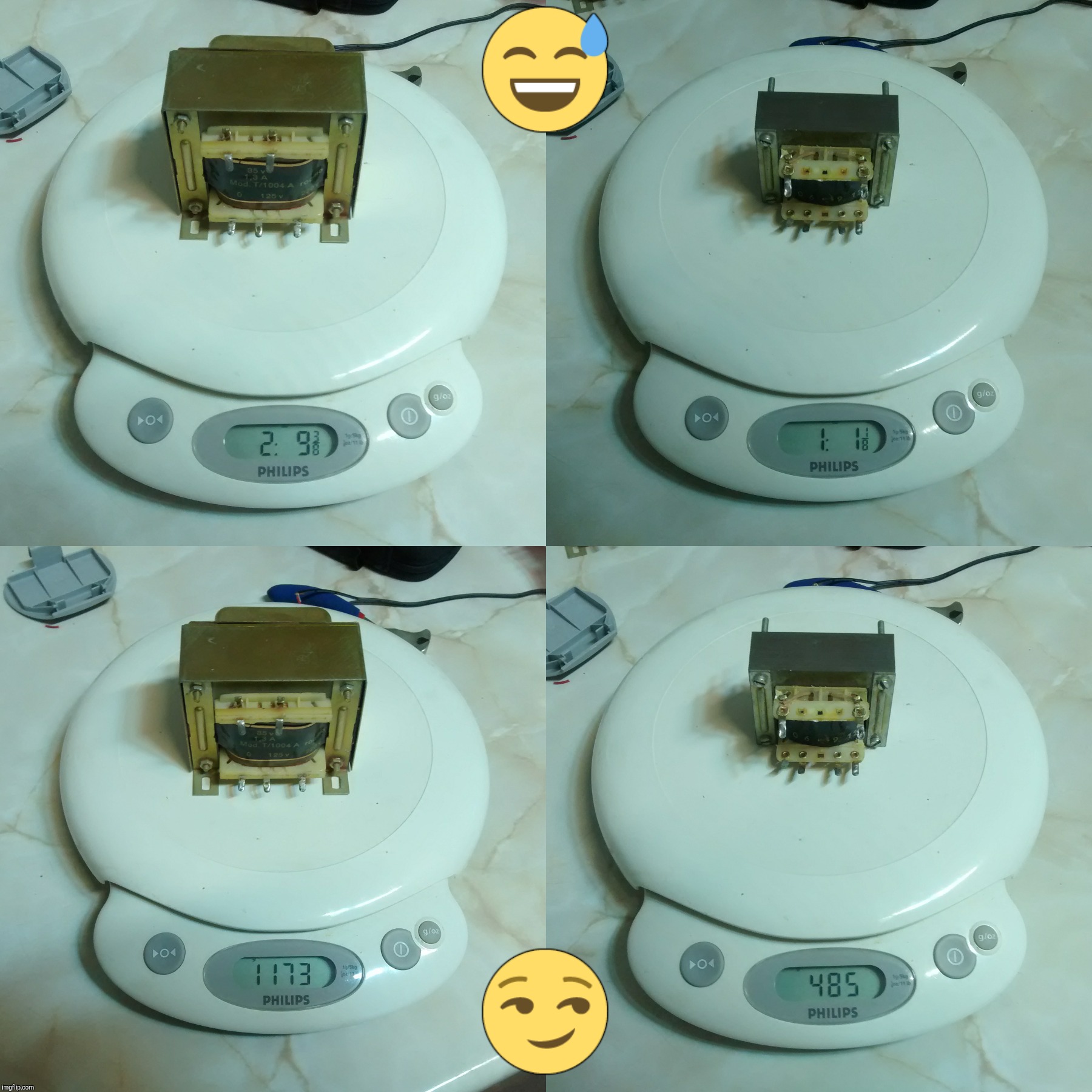
Well, I'll probably make an inductor out of an old school AC/DC brickwalwart's transformer secondary windings. I have a 230VAC/9VDC transformer (edited: this one is a keeper, using it to power up the kitchen scale you can see some messages below), a multi-DC output 220VAC/(12/9/6)VAC transformer too, and a rare and chunky 230V/35V unit. I'm gonna put a 9V cell in my used kitchen scale to see how much it wheighs. ;)
Cheers ^:)
P.S.: fixes and updates here & there (2016/05/0, 07:17).
Ooops!
With respect to the size, my plan is to make it at least big enough to output 4’8A of current without much effort so, if make it a bit smaller than this thread’s example replacement, it should handle 5+A well.
Cheers :partying_face:
P.S.: I should not afford more than 10mm driver board height, or else I’ll have to chop a bit the baseplate’s internal pill support heatsink, LOL!
Some of those transformer Cores are just held together with spot welds. Hit it one good hard whack at the seams with a cold chisel and it will pop right open and then you can pull the windings right out. If you were just wanting to salvage the wire that’s how I would do it.
Well, I was just editing my #26 post above, but realized it was such an overhaul I'd better post something new, LOL!
The brickwalwart, a linear PSU, remains “whole”.
The small one, as said above, is a 220/(12/9/6)VAC transformer.
The big-ass lady is a (220/115)/35VAC transformer of unknown amperage; I bet it does 2A output for sure, I once tinkered with a smaller 24VAC 2A unit and it happily campered at 3+A so, 3A sounds nice.
What is more, since the official mains voltage is now 230VAC (where I live I get 240-250VAC hehehe), if I connect mains into the 115VAC primary winding, the output will be 70+VAC RMS (100+V peak). Thinking in building me up a nice CC/CV buck power supply. 8^)
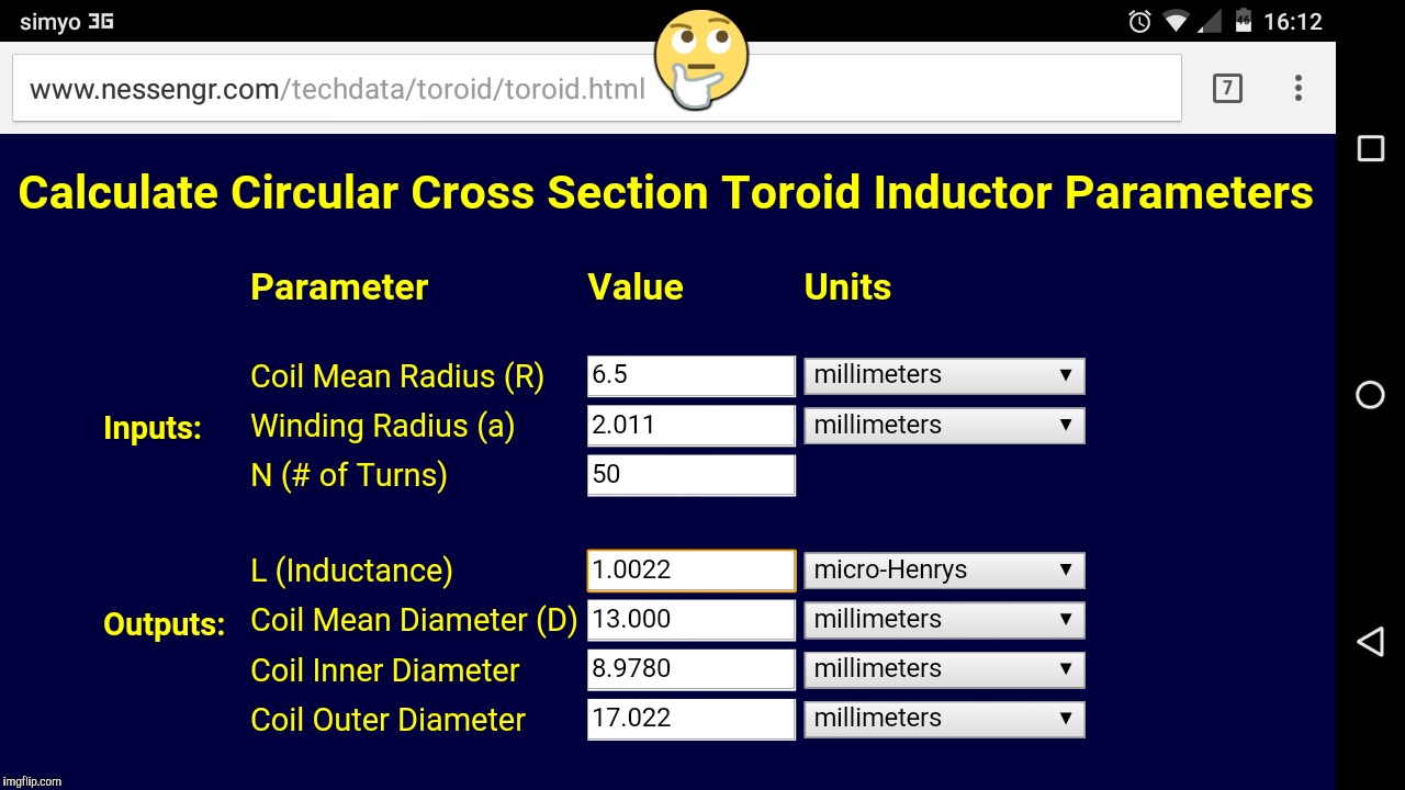
I’ve taken a look at the windings of the small AC transformer, seems to be AWG24 solid copper wire. I think I can make a coil small enough to fit in the limited space I have (≈∅18’75mm pill internal diameter) and be good to perform well for a couple extra amps (up to 5). Figures:
Sounds good enough?
Cheers :partying_face:
P.S.1: about 650mm (25’59”) of wire lenght leads included, for a total of 56’264mΩ coil resistance.
P.S.2: not nice, too much resistance. I may roll 2-3 coils in parallel, reducing diameter a bit, less inductante but higher current handling; over-analizing… :person_facepalming:
In the review, HKJ (?) complains about the fact that the driver (supposedly a 3A unit) pumps out too much current to the led and, after a quick gaze at the upper right photograph of the review, the evidence is clear: he received a pre-modified driver, a 0'33Ω resistor can be clearly seen stacked over two of the regular R200s onboard (there's a third one by the other side). As the CC reference voltage is 0'2V, applying Ohm's Law: I = 0'2V / 0'33Ω ≈ 0'61A; this precisely matches his measurements: 3'6+A of driving current.
Good to see it is quite efficient for driving 2S emitters.
This page answered my question. I thought maybe you were just roughly ballparking it but I see now you are using a calculator.
I see the HAM guys concern themselves with core recipes and frequenceis. Is this not an issue with LED drivers?
What will you use for a core?
Forgive my ignorance, I’m not an EE.