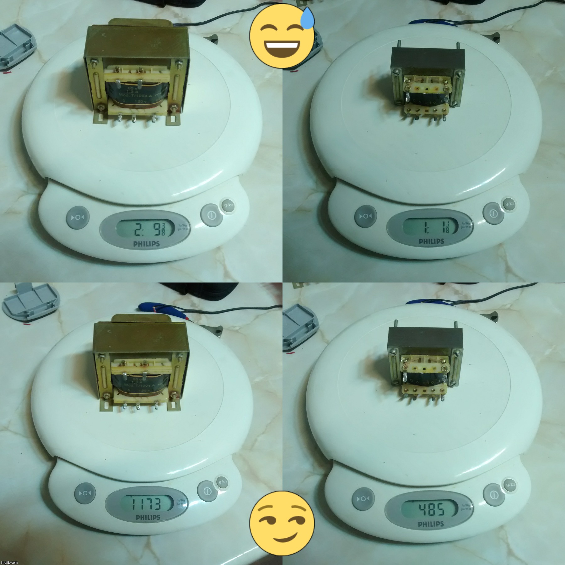
Well, I'll probably make an inductor out of an old school AC/DC brickwalwart's transformer secondary windings. I have a 230VAC/9VDC transformer (edited: this one is a keeper, using it to power up the kitchen scale you can see some messages below), a multi-DC output 220VAC/(12/9/6)VAC transformer too, and a rare and chunky 230V/35V unit. I'm gonna put a 9V cell in my used kitchen scale to see how much it wheighs. ;)
Cheers ^:)
P.S.: fixes and updates here & there (2016/05/0, 07:17).
Ooops!
With respect to the size, my plan is to make it at least big enough to output 4’8A of current without much effort so, if make it a bit smaller than this thread’s example replacement, it should handle 5+A well.
Cheers :partying_face:
P.S.: I should not afford more than 10mm driver board height, or else I’ll have to chop a bit the baseplate’s internal pill support heatsink, LOL!
Some of those transformer Cores are just held together with spot welds. Hit it one good hard whack at the seams with a cold chisel and it will pop right open and then you can pull the windings right out. If you were just wanting to salvage the wire that’s how I would do it.
Well, I was just editing my #26 post above, but realized it was such an overhaul I'd better post something new, LOL!
The brickwalwart, a linear PSU, remains “whole”.
The small one, as said above, is a 220/(12/9/6)VAC transformer.
The big-ass lady is a (220/115)/35VAC transformer of unknown amperage; I bet it does 2A output for sure, I once tinkered with a smaller 24VAC 2A unit and it happily campered at 3+A so, 3A sounds nice.
What is more, since the official mains voltage is now 230VAC (where I live I get 240-250VAC hehehe), if I connect mains into the 115VAC primary winding, the output will be 70+VAC RMS (100+V peak). Thinking in building me up a nice CC/CV buck power supply. 8^)
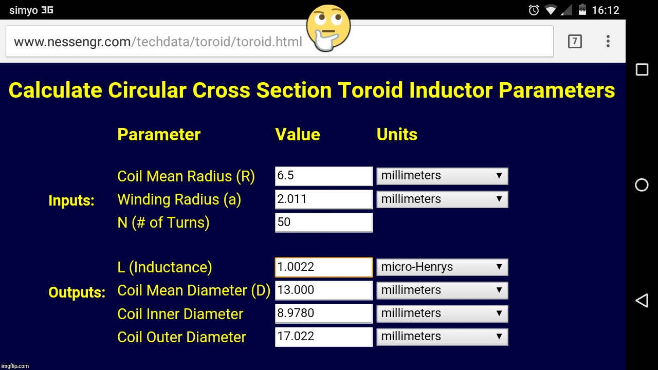
I’ve taken a look at the windings of the small AC transformer, seems to be AWG24 solid copper wire. I think I can make a coil small enough to fit in the limited space I have (≈∅18’75mm pill internal diameter) and be good to perform well for a couple extra amps (up to 5). Figures:
Sounds good enough?
Cheers :partying_face:
P.S.1: about 650mm (25’59”) of wire lenght leads included, for a total of 56’264mΩ coil resistance.
P.S.2: not nice, too much resistance. I may roll 2-3 coils in parallel, reducing diameter a bit, less inductante but higher current handling; over-analizing… :person_facepalming:
In the review, HKJ (?) complains about the fact that the driver (supposedly a 3A unit) pumps out too much current to the led and, after a quick gaze at the upper right photograph of the review, the evidence is clear: he received a pre-modified driver, a 0'33Ω resistor can be clearly seen stacked over two of the regular R200s onboard (there's a third one by the other side). As the CC reference voltage is 0'2V, applying Ohm's Law: I = 0'2V / 0'33Ω ≈ 0'61A; this precisely matches his measurements: 3'6+A of driving current.
Good to see it is quite efficient for driving 2S emitters.
This page answered my question. I thought maybe you were just roughly ballparking it but I see now you are using a calculator.
I see the HAM guys concern themselves with core recipes and frequenceis. Is this not an issue with LED drivers?
What will you use for a core?
Forgive my ignorance, I’m not an EE.
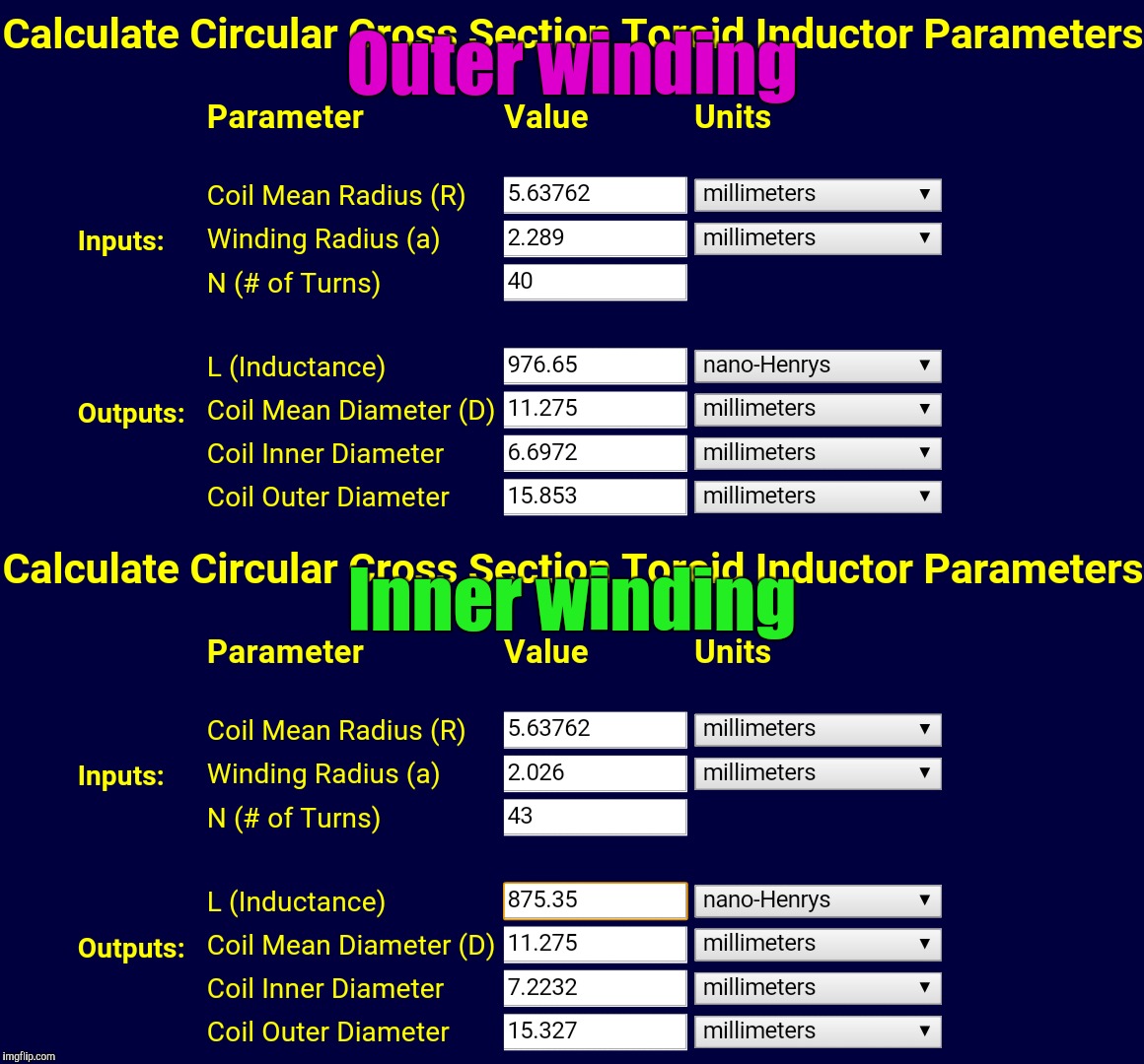
A more adequate design with two stacked coils in parallel, with about 461'61nH and slightly below 25mΩ, which I find it'd required for 5+A of current handling. Air core.
No problems with RF noise in toroidal inductors: a virtue of their geometry.
So far, this is what I've come up with. I'm no literate in these matters, though.
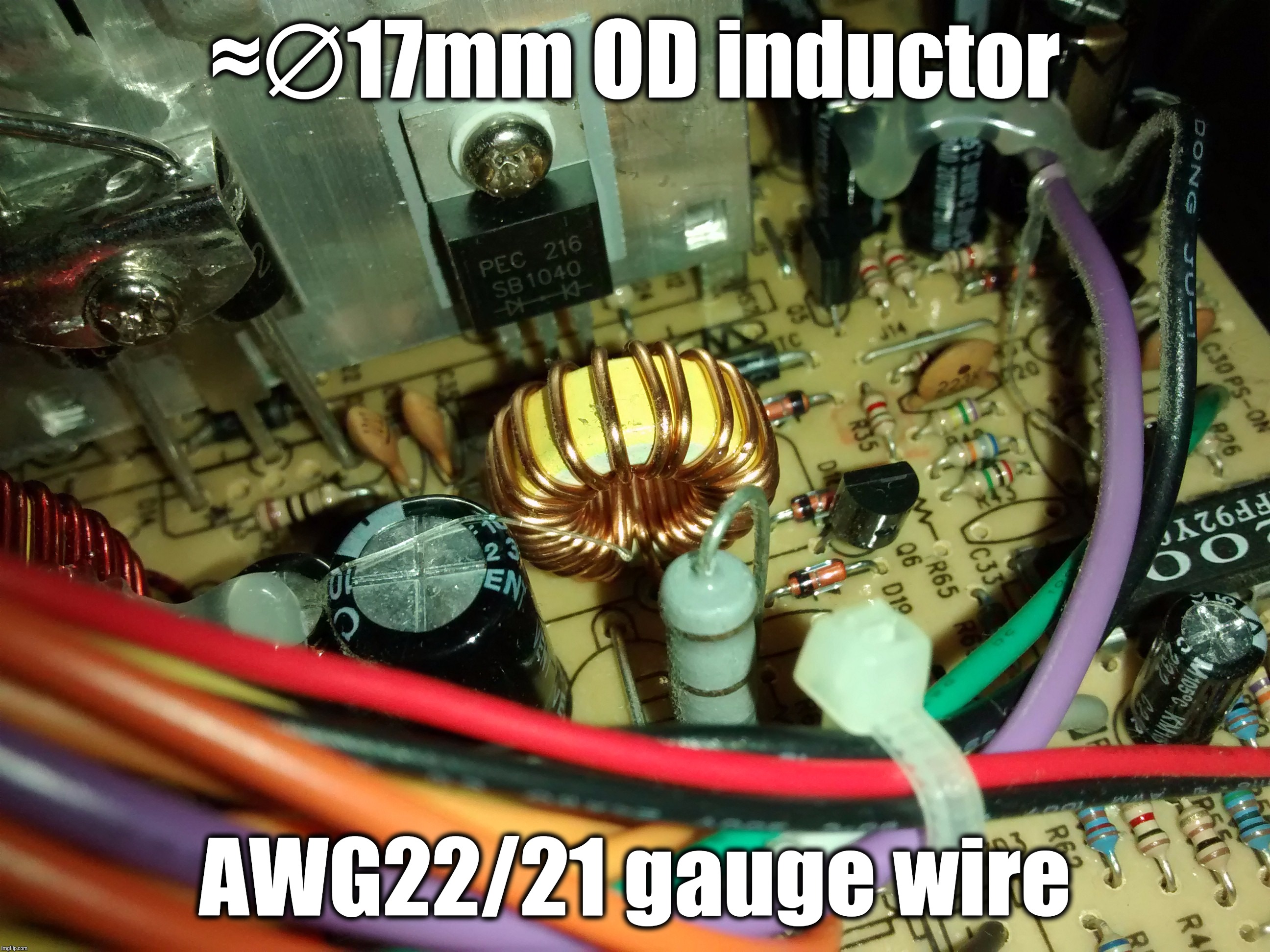
Of course it doesn't, yet it looks ≈ to the inductor the OP used, size wise. If I deem it to be too chunky, since that ought to be built around some ferrite core, I can always unroll a chunk of it: half of the wire should still provide ¼th of the inductance (seems to provide plenty) with just ½ of impedance. A third of the roll would still provide ≈9μH at ⅓ of impedance.
I do know Jacksheesh about inductors, mind you.
Cheers ^:)
P.S.: the inductors in the test photos look to have approx ½ of the winding lenght with respect to the pair I've bought so, my pliers will talk; of course there's still plenty of time for someone to chime in with more enlightening information…
No need to chop off anything! I've ordered a couple of inductors so, I'll dismantle one and then re-roll its wire carefully around the other's winding!
It's gonna be a massive amount of copper wire coil attached to the board so… free heatsink!
Sounds that good?
Cheers ^:)
Original date of post: 05/05/2016.
Edited for make-up of broken unimportant image links.
These are the inductor cores I've bought. Because of the relatively high output current and me deliberately wanting to keep efficiency as high as it could reasonably be, I've gathered some more info as to confirm my theory of increasing current handling through winding in-parallel magnet wire and:
Well, what is said there confirms my theories. I'll be able to wind up 30 turns of twin in-parallel AWG24 magnet wires for about 3'2μH of inductance with half of the resistance compared to single AWG24 winding.
Cool!
Cheers ^:)
Original date of post: 05/05/2016, or soon thereafter.
Edited for make-up of broken unimportant image links.
Of course the inductor cores came home long ago, and I've yet to gnarl with the transformer for the windings (took away the screw & nuts at its corners; most probably I'll have to use cut-off disks over its metal frame, seems it was not built to be disassembled).
On the other hand, I'm also upgrading the driver's SS34 schottky with a 20SQ045 (LOL!) in order to achieve somewhat higher efficiency and guarantee reliability.
I'll post some beautiful pic(s) once it's done.
Cheers ^:)
Original post date: Sat, 08/27/2016 - 12:09. Edited for a little fixup.