Btw I will be making a new version of Rev5, with pots on the underside of the board, and 2 channels of 3 emitters instead of 3 channel’s of two. That will work better for how I have been using them.
Yes! That would be a welcome change for me too
Thanks Pd
It’s a little tougher outside the US a the moment but a bunch are on their way to Amsterdam yet as more requests keep coming in from different parts of the globe Simon is going to list them in his store soon. If you are ordering anything else from Simon’s Aliexpress store just send him a message with your order and he can throw them in with whatever else is being shipped.
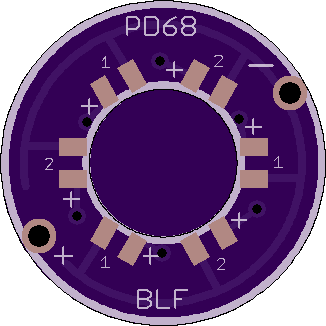
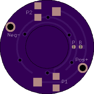
Here we go, 16mm Rev5.2. One potentiometer per three emitters. Keep in mind potentiometers will probably need to be adjusted before installation in the light, as they will be hard to access once everything is soldered down.
Bridge point “P” (parallel) to put all six emitters in parallel under the same pot.
Bridge point “B” (Bypass) to bypass the pots and directly connect the LEDs to the Pos and Neg terminals (will need to use pots or resistors on the switch pcb, such as the Rev4 board.
Hey pdog… can you make the center hole a little larger so that it will fit over the square body switches?
Sure, won’t be tonight though, the desktop just got shut down.
Can you measure what size the hole needs to be, and how big the base of the switch is? (to see where I need to put the pos/neg terminals and resistors)
What version of 5 do you want it modeled after?
I have been sanding down the switch to fit the ring! Switch post is 8mm, body is 12mmX12mm and contacts are on opposing corners.
Do you want it more like Rev5b, 5.1, or 5.2?
I like the 5b… the one with 3 resistors and 6 leds.
I think you mean the normal 5.1 then. (5.1x is the crazy individually-addressable version). The nomenclature is a bit out of hand, but I don’t know what to do about it
The one I really like has 6 led pads on the top and 3 resistor pads on the bottom and 2 wire vias. If I had the pots, I would maybe go that route since they can be adjusted…
Pots are pretty nice, just so you don’t have to constantly be soldering/desoldering to dial in the brightness. If you want I can try to do the pads for pots and then you can bridge resistors on the pot pads. Or I can do the three-resistor setup and if you want to upgrade to pots later you can just pair these boards with the Rev4 pcb at that point.
Really whatever you want.
It would be fine if they were 2 sets of 3 leds that could be pots or normal 0805’s. I may try to find the pots. I do like the option of having 3 different colors.
The 12x12 switch base will be the tough part for the pots, as they are 3x3mm each. It would have to be a pretty big ring
Really, just the standard ring with 3 resistors would be more than fine. I tried to ream the centers, but that did not go well. I would be after the 17mm ring, maybe a set of 19mm’s as well.
Have not received the clear gaskets for the S2+ yet, and I do not know how many Simon has sent to me. When they arrive I will report, and also will put one in a red S2+ that already has six nice red leds that for now are illuminating just the inside of the tail.
Here it is. Unfortunately I couldn’t make a 17mm version, as the base of the switch is too big. Even on the 19mm diameter the resistors are pushed almost all the way to the edge. Interior ring is spec’d at 8.4mm, probably will be 8.1mm when you get it from Osh.
I will try it… the resistors on the 17mm that I have used so far have set on the switch but it seems to work fine. Will try to get a pic this weekend for you…
If you are fine with the resistors riding on the switch then I can chop it down for you. I just thought that would cause problems with fitment.