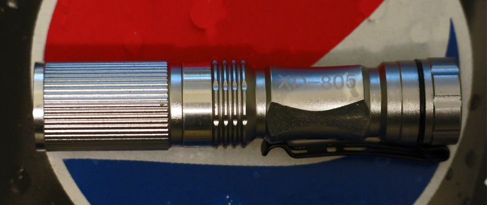
Is a chinese no branded one you can find on ebay, aliexpress and many other sites.
I got it from this seller: Henny Liu’s store , but i don’t recommend him/her as i got different clip from which is shown on advert images, so random version could be sent.
I need some help. So far everything I’ve done has had a perfectly circular milling layer. How do I do other shapes accurately? Like an SRK driver with the tabs, or a tailboard in the SRK “flower” shape or for a ZY-T08?
Easy for you to say Richard! But this comes from a guy that build a D01 contact board and could not make a basic FET driver fit on board… I really suck at that program.
I just draw wires on the milling layer. If I need part of a circle I draw a full circle in the reference layer, than draw an arc in the milling layer and trace the part of the full circle in the reference layer that I want. I’ve never used the commands RMM suggests, I’ll have a look at them next time I need to do something like that.
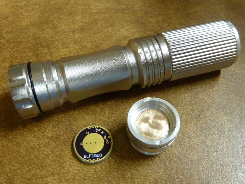
Thanks DEL. The latest items I’ve ordered and just received thanks to this thread is the 15mm 7135 driver boards and the boards for momentary switches. Hopefully I can get a driver to work. :person_facepalming:
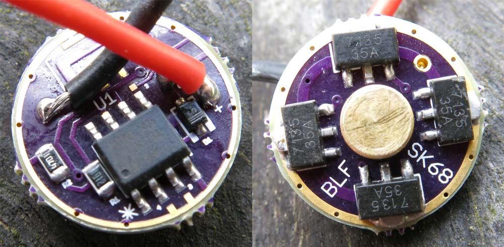
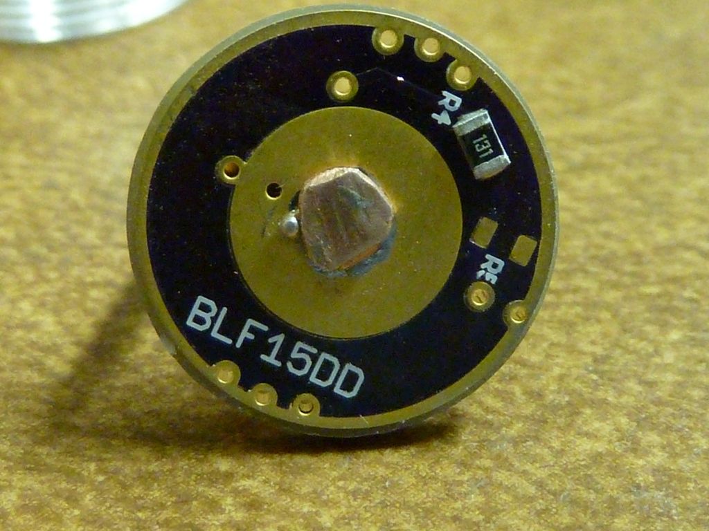
Wow. What a mission. Well for me it is anyway. I have just happily, after many failures over along period of time, managed to build my first working driver. Its the 15mm SK68 driver by WarHawk here.
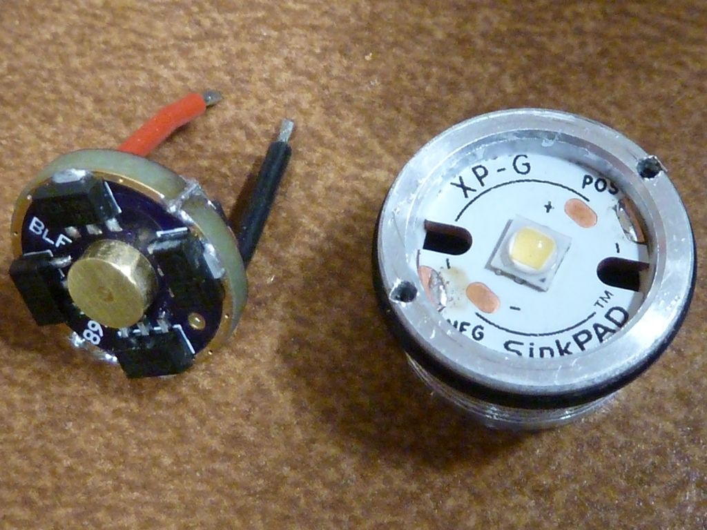
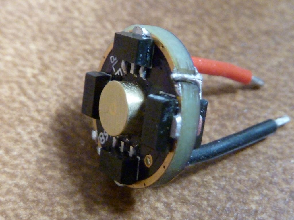
I used an old 7135 driver for parts that never worked, flashed the MCU with TK’s Biscotti and we had light. To everyone involved, a big thanks. Yes there were lots of you here that has helped me over an extended period of time from soldering, flashing and answering many questions. YAA HOO.
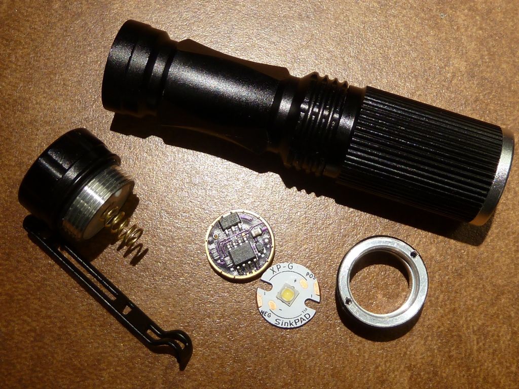
Not quite this time. I’ve used this light peering down machined holes for along time now. Its ideal being a small zoomy being able to adjust the beam pattern to suit what your looking at. However it had a next mode memory driver with the dreaded flashy mode. The pencil mod on the capacitor only made it cantankerous. Due to a suitable driver not being available put up with it until now.
Another chip was added to make it five in total with an XPE2 Torch led used for lighting purposes. Shims were added to only allow the zoom I required. Dont laugh to hard at the flashlight itself. Yes it was cheap and very nasty.
I've done a few of those a while back using different drivers, FET and 7135's. They go pretty fast, hard to keep them around. I shorten the sliding piece to create a wider zoom area - works for most of them.