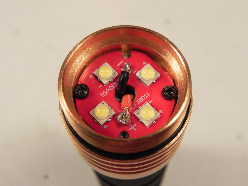
It really looks like the outer area of that MCPCB is all positive. If that’s the case it’s a bad design and a quite dangerous one. Could be fixed with isolation discs under the screws, but there isn’t even enough space for the screw’s heads…
Another good question: what’s the current draw? Lumen numbers are lower than I expected. I’m getting about the same numbers with three 219B-V1 and 5A regulated driver (stacked 105C)…
And I have one more question: Kenjii wrote that there’s a front glas on top of the optic. How many O-rings are there and where are they placed?
Might be an idea to put some thermal adhesive under that MCPCB, screw it down & reassemble the light until it sets then remove the screws if that’s positive traces under those heads…
That’s a very good idea, only thing to think about is if you ever plan to swap emitter boards thermal adhesive could make that difficult.
I sometimes rotate the mcpcb so that it overlaps one of the holes going to the pill side and then you can use a small screwdriver bit or the like to apply pressure from the backside to lever the board away from the adhesive.
Oh boy, I hope this is not becoming another flashlight design fiasco… it´s not rocket science to make a clean und secure flashlight and driver design, no?
K.
The dielectric layer is normally pretty though and doesn’t wear too easily even with the tightened screws, but if that becomes a problem they could simply reverse the polarity and reflow the LED the other way around, so if it shorts it will only lose modes and not become dangerous. Another fix would be if they used anodized screws and a plastic washer disk on top.
It’s just a light folks. Chill.
Nothing that can’t be adjusted. If the screws bother you, remove them. Just put some Arctic silver thermal paste (not epoxy) under the mcpcb. The pressure of the optic on the mcpcb from the optic, once it’s tightened down is more than adequate. I doubt it makes much difference any way you look at it.
Four nichias with a 16350 are only going to put out what they can.
I build a lot of DD 14500 triple XPE2s, and the tail current never varies between 4.2A and 4.5A no matter what’s done or what batteries, protected or unprotected. It is what it is.
Thanks Kenjii, right amount of o-rings at the right spots, that’s good news. EDIT: Oh boy, I think I read what I wanted to read…BUT:no o-ring between optic and glas?How is the optic kept in place? Does the glas make direct contact with the optic?
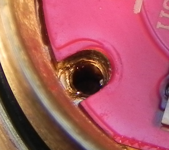
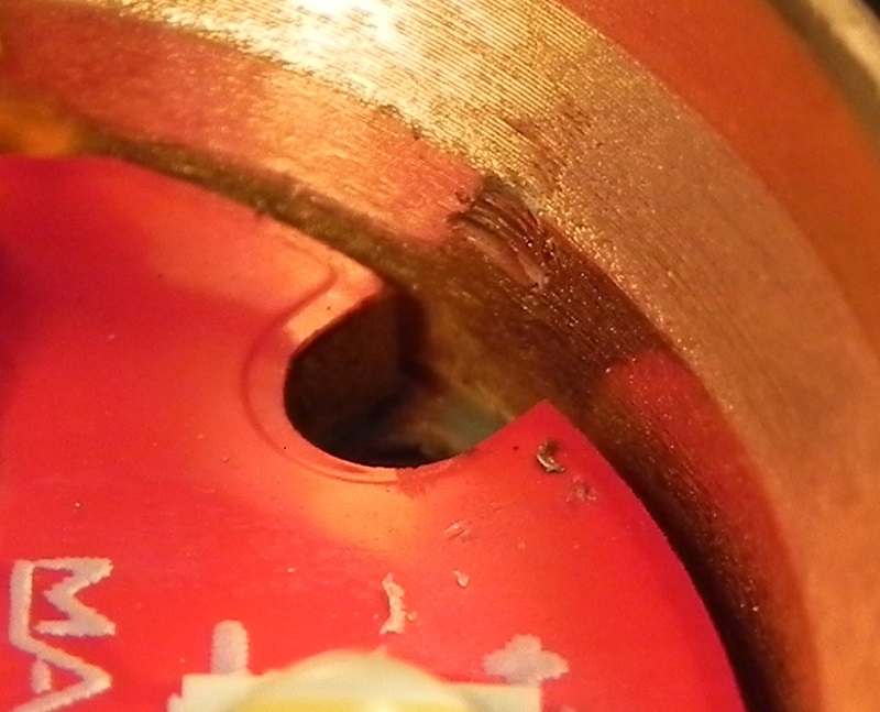
Well, positive trace goes almost to the edge, they should’ve kept a bigger distance from where the screws go at least.
The smaller screws look like a better fit, but based on those closeups it does seem the + side is right under the screw head… as long as that solder mask holds up it would be OK, but that is still rather poor. All it would take is for as screw to be put in crooked or a screw with a rough underside to the head to cut through the mask and create a short!
I think screws were never a consideration in designing that MCPCB. Usually you have optics with 4 legs and the better way, IMHO, is to have the pins a bit longer to protrude past the MCPCB into holes in the shelf locking everything in place and preventing rotation.