You bet PD, and yes had to really look hard for that silver lining but once discovered I was literally thrilled, I don’t know how I can go so goofy over a couple switches but certainly did, and after the swap sat here with the lights out and switches on and just enjoyed ha ha ha
Thanks for the mention Matt regarding a embossing tool soldering station,
I think I get what your referring to, sort of a rework station, surface mount work, heat gun etc, frying pan.
If you happen to have a link and the time I’d sure appreciate a point in the direction,
I believe the rework station I saw was at a place called All Spec, not positive if I’m thinking down the correct lines here.
Anyhow, no wonder Simon wouldn’t sell me a few metal S2+ switches a few months ago, I sure haven’t been keeping up and just noticed the S2 work, wow, they sure do look good,
Simon’s next release will probably be sporting some really nice upgrades, the S2S+1
My reflow iron… search for DARICE EMBOSSING MULTI-PURPOSE HEAT TOOL, 320 WATT NEW on ebay…
Don’t laugh to loud, works great! Thanks PD!
Thanks Matt, I was just looking at some rework stations, and a lot of accessories that I have no clue about, like assorted little cups that appear to go over the part and hot air heats the part up and melts the solder or so it seems, So laugh at you Matt.? Now that’s funny,
I have a lot to learn yet and really glad you mentioned this,
I’ll take a look at this one in the morning,
All I need is a decent beginners station, maybe something that can be upgraded as my skills improve, don’t know.
Thank You Matt…
I build a nichia light today with nanjg 105c and nlite firmware. I used Rev 5.1 LTC board. Lightning works fine…but when I tap I cant switch modes. The main emitter shut down when I tap. I didn’t use a bleeder and no resistor on the ltc board, just 2 leds in parallel with a bridged R1 spot. Maybe this problem is known and somebody can help?
Thank you!
Edit: I found another interesting detail…when I use a battery with voltage < 3,9V it works. >4V did’nt work. What do you think?
sounds like the MCU is never shutting down. Try a bleeder.
Finally i got all the parts and gave myself a crack modding.
the resisters and SMD are tinny and it hurts my eye welding.
Destroyed 2 LEDs while over welding and lost 2 resistors dropped on ground but successfully put together.


Looking good! Well done. ![]()
why do you think a bleeder could help?
Theory: It sounds like whatever current your tailcap ia drawing, it’s more than the voltage divider resistors on the tailcap allow through, so the extra current is being pulled through the mcu itself, and it’s enough power to keep the mcu awake, and not thinking the switch was ever pushed. A bleeder should divert enough power past the mcu so that it functions normally.
Hi all!
I just received the new Astrolux S41, and for what i believe i have come across in the long thread dedicated to this light, someone mentioned the tailcap PCB is ready for lighting but not populated.
If someone managed to get it working, i would be happy to see a component list and little how-to… :innocent:
Thanks
Quick report - got a tailcap working perfectly in a Convoy S2+.
Notes:
- You want to order 0.8mm boards, not the standard 1.6mm. The normal ones are too thick and the tailcap assembly doesn’t sit right (too far from metal switch, too thick to tighten down the retaining ring more than a half turn).
- I used a 47 ohm bleeder on the driver and 400 ohms on the tailcap. You definitely want a 1:6 ratio or lower (going off what someone earlier in the thread pointed out - thank you!). The 450 ohm total is necessary to see the low-efficiency red LEDs through the rubber. This means the battery will drain in about two weeks but I’m ok with this, can always loosen the tailcap to lock out.
- On the MTN-17ddm driver, you want to put the bleeder before the diode (NOT across the capacitor). I actually ended up using a 1/8 through-hole resistor and soldering it between the spring and the ground ring since my SMD resistors were not quite long enough for that and the 1/8w doesn’t interfere with anything. Modes work fine for me.
I’ll post some pictures when I have some time to get the camera out. Thank you for all the hard work PD86 and everyone else!
Hi! I want to do this lighted tailcap in an X6. I found that I need the v5.1 version for 14mm boot, and I ordered high amp tailcap board too because it will be a triple XP-L setup. But what size leds I need under the boot to fit nicely? 0805 or 0603? Everything else is clear for me. Thank you!
I have made them with both sizes of LED’s. I think technically it is designed for 0805’s. If nobody answers with authority I can measure the pads tonight. Might check the info in the thread, should be in the section that introduces the board.
All boards are designed for 0805 except the crazy looking one
Thank you! Now I will order some 0805 leds for it.
A verson with 1206 LED pads was requested so here it is:

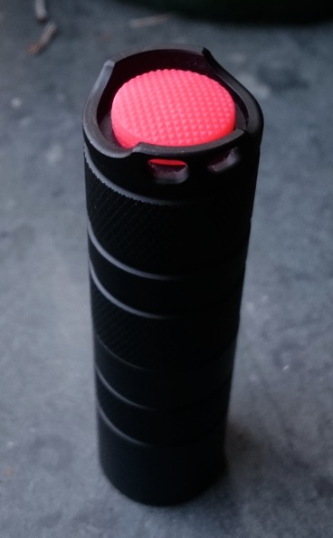
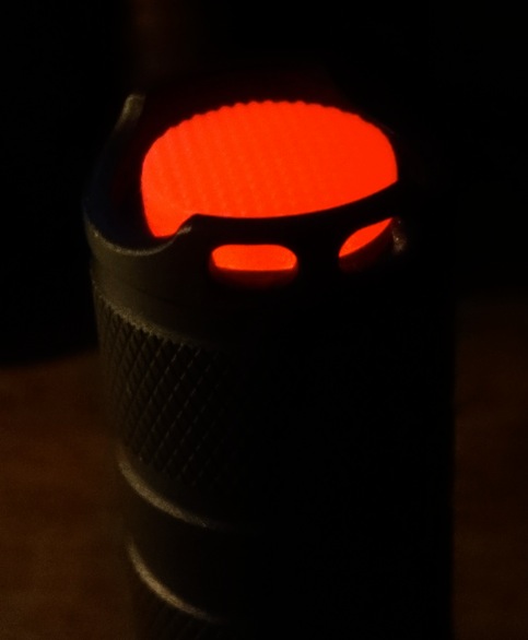
Yesterday I made a lighted tailcap on a Convoy S2+ shorty that has a triple Nichia 219B red emitters, I used red leds for the tail of course. It proved useful today already when supervising a photograpy school project in a dark room (a blinded class room), I could find the red flashlight back immediately all the time :-) .
What is new (to me at least) is that I did not use a transparant tailcap but a red one, it is fairly translucent for red light. Here it is by daylight:
parts list:
-Qlite driver from intl-outdoor link
-0805-size bleeder resistor of 470 Ohm on the Qlite (without the resistor everything goes wrong with the UI)
-PD68's dumb 16mm tail washer circuit board with 3 pairs of 2, makes 6 led pads link
-3x 5.7 kOhm 0805-size resistors before the 3 strings of 2 leds
-6x 0603 size red leds from Fasttech link
-16mm red tailcap from kaidomain link
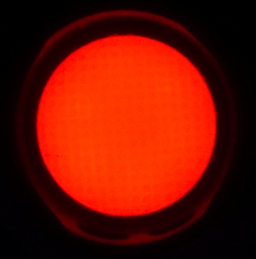
With these resistor values and leds, the Qlite's behaviour is entirely normal. The lighted tail draws 1.02 mA, so will empty the Sanyo 18500 cell in between two and three months. The light is clearly visible in the dark at a distance without being too present, a good locator brightness. The entire tailcap is very evenly illuminated, thanks to the red tailcap that diffuses the light more than the transparant one.
Crazy idea, would it be possible to add a photoelectric sensor in the tail, something like this ?
Run time could possibly be extended as then we’d only need to run the tail LEDs when ambient light drops below a certain level. Just a thought :).
That would be interesting, certainly. Other than the problem of available space, the cost is prohibitive. We would have to buy 3,000 of them.
Well that one is available from Mouser in qty 1 @ €1.7, but there could be better/simpler options for the same task.