Attiny25/45/85 FW Development Thread

I can just tag it with “GPL” in the metadata file for now, but to be fully legit the code needs a comment somewhere in the header. This explains how:

https://www.gnu.org/licenses/gpl-3.0.en.html#howto

… and since the license itself is written by lawyers, this explains it in more plain language:

https://www.gnu.org/licenses/quick-guide-gplv3.en.html

Meanwhile, the BSD license could fit on a napkin. :slight_smile:

Oh, and since you own the copyright, you can change or cancel the license any time you want.

I’ll grab the updated version before adding it.

You’re also welcome to change a branch of the repository and propose merges if you want. It’s extra effort and overhead though, so I normally do that part. And I’m still considering moving it from Launchpad (bzr) to Github (git), since git is more popular. Any preference?

If you are offering to do that part I certainly don’t mind not doing it… I can spend that time on firmware… or writing instructions for it (more work than one would think).

No preference. I’ve never used any of those.

Just posted the latest smooth ramping version of Narsil up on my google docs share, with the updated manual in docx and PDF format.

The share is: Google Doc 254585 Support Shared Drive

Just to make it clear, it's configured for a FET+1 driver, with a 350 mA 7135 (not 380 mA). This is an important detail for the ramping to work properly. Other ramping tables can be built and used easy enough to support 380 mA chips, or only FET, using TK's utility. In fact I need to modify it myself to work well on one of RMM's SRK 7135 drivers. Also moon mode would need to be changed/tweaked based on what you can use as the lowest PWM value, depending on the driver (FET, 7135 350 or 7135 380).

TK - if you get a chance, you can post it in the repository - your same GPL license that you use is fine. Think it's just an update anyways.

Very nice, thank you very much for sharing Tom E! :beer:

I just adjusted the code for modes and turbo step-down timings for my DQG mod.
.hex file got compiled just fine.

As soon as I have more time, I’ll swap the R1 & R2 resistors and flash the new firmware.

Anybody knows which 7135 (350 or 380 mA) is on the X6 driver? How can this be determined?

I think it's a 350 but not sure. Easy test is in Narsil, set a fixed mode (there are many sets with a max 7135 mode), then measure amps. Of the 350's and 380's we use (most bought from FastTech), the 380 is clearly labeled as 380 while the 350 is not.

I just flashed the new Narsil with ramp and replaced R1 & R2 with 220K & 47K resistors. Those 0805’s are some little pieces to solder!

Firmware is great. Ramping is a really nice feature!

I have a few issues though…
On battery check mode, I now get 1-1 blink (1.1V?). On the “old” Narsil before the resistor mod, it worked really accurate.

Also the parasitic drain still reads 0.01A on my UT210E.

Maybe some resistor has got a bad solder joint? Or won’t the driver work at all in that case?

Edit: On 100% 7135 the tailcap measures 350mA, so that should be O.K.

The 1.1V blink means an error happened and it couldn’t measure voltage. If you flash battcheck.c onto it, it’ll probably blink out 255 every time. It’s almost certainly a physical problem somewhere on the driver, but I’m not sure where exactly.

Did you remove the bleeder resistor?
And I don’t know if we can trust clamp readings at this little currrents.

Not that I’m aware of … Thanks, I guess I kinda missed that… How do I recognize the bleeder resistor?

It also sporadically jumps modes now, for example from moon to a high mode…

At the banggood X6 driver it goes from the LED+ pad to ground, labelled 471 which means 470 Ohms.
How many amps does your mod pull at turbo?

Thanks for the info TK & Flashymike! Does removing this resistor remove any functionality? Like mode memory or something? Sorry for the noob question :wink:

Just did a quick tailcap check, on a full 30Q it pulls just short of 13Amp.

It is only needed for a lighted tail cap on lights with tail cap clickies - which you don’t have, I assume.

With that high currents I wouldn’t recommend the Banggood X6 driver. At currents above 9 Amps it tends to reset the mcu due to inductive spikes. I’ve read the Mountain Electronics drivers are better.

Yea, for 17's, I'm using the MtnE drivers exclusively now - got all the parts in, including the 0402 resistor - talk bout small... On the MtnE boards, I use 191K resistors for R1 because the resistors are after the diode, not before, opposite of wight's drivers.

Dutcheee - I hpoe you don't mean in that order as you said: I just flashed the new Narsil with ramp and replaced R1 & R2 with 47K & 220K resistors

R1 should be the 220K, and R2 the 47K. I haven't used the bleed resistor in any of my driver builds, 85 or otherwise.

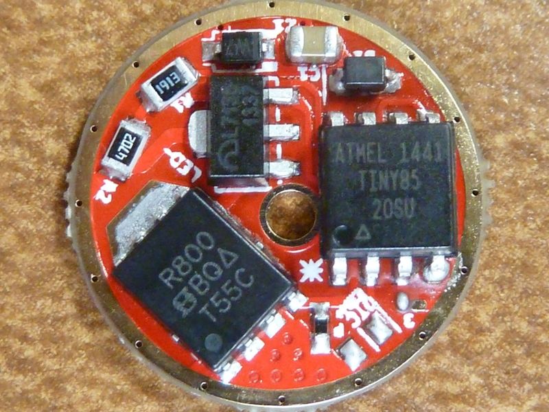
Here's a pic of a working MtnE driver, the MTN17DDm, v1.1:

This evening, I'll double-check battery level checks on these MtnE boards. Every 85/Narsil I've built with the new ramping support battery check and LVP work fine - I've tested I'd say about 6 working lights so far w/latest Narsil, 3 of which are in SRK style lights, doing 15A to 20A each (3X modded M6, 4X clone, 5X clone).

Last night I just updated my SWM C20C with the ramping version. It blinks out 3.9v and with the cell removed, it measures 4.007v on a Fluke DMM. I consider that close enough, but the driver is a wight driver, so I'm using the 220K/221K resistor for R1.

Important Note: To properly measure parasitic drain, you must hold the probes across the batt- to the housing for several seconds, I think it's about 6-8 seconds. I added this delay to the firmware intentionally - it's a delay before going into sleep mode. I just did this on my C20C light, and measured 0.02 mA, whichs is 0.016 mA rounded to 2 decimal digits. Looks like this Fluke I'm using at work (175 - true RMS DMM) is limited to 2 decimal digits.

I measured 4.85 mA for those first few secs before it drops. The 4.85 mA is probably the MCU's draw in normal running.

Thanks for all the quick replies :+1:

I believe so, but I’ve used this driver at high temp. and 13A with the AT85 mcu for quite a while now without problems.

I’ll remove the bleeder and see if this fixes anything.
It only jumps from moon to some high, not being turbo.
From low and higher settings (just above moon and up) I haven’t seen it “jumping” yet.
At the high amps, all works well. I’ve set the turbo stepdowm to 15secs and it does so every time.

If removing the bleeder resistor doesn’t fix it, I’ll replace the original resistors and see if that fixes it. Parasitic drain isn’t that much of an issue, because I tend to lock it out anyway.

And then I’ll order some boards from MTN, hoping to get things right in the long run…

Yes, offcourse. I replaced them 1 by one with a factor 10 bigger. That was a typo.

Oops, more details added to post #949 above.

I don’t know about the ATtiny85 but the standard Banggood BLF X6 driver has a ATtiny25 mounted. This mcu has problems with high Amps, the ATtiny13a on the same PCB doesn’t. Interesting to hear the ATtiny85 does not show this problem, perhaps I will give it a try. Have you used your high drain cell with this mcu earlier or did you use lower drain cells?
Is it possible to mount the ATtiny85 with a soldering iron in the place of a ATTiny13a or ATtiny25 or do I have to reflow it?

I use hot air reflow, but it's possible to hand solder I suppose - just need to do a good enough job wo you can still clip on to the MCU and re-program, You have to bend the pins of course - can be a challenge - just a warning. With the bent pins, it's actually easier to program in place.

I for one would not use the BLF X6 driver - don't trust the quality. 25/45/85's have all the same problems with our standard circuit design. My fixes include:

  • pull down resistor on the FET gate, from 12K to 20K, high ar 47K or so
  • for C1, double up the 10 uF cap (add one stacked) -- BLF A6 uses a 12 uF cap, not 10 uF!! Pull it and test it if you don't believe me, or, maybe they are sneak'n in 10's now, and that's why it's flaky
  • add a 0.1 uF cap across pins 4 and 8 (grnd to VCC)

The combo of all 3 of these always works, every time, for me. Sometimes you can get away with just the FET gate pulldown, sometimes FET gate pulldown and the 0.1 uF cap. This is why Richard has all these extra parts on his driver (zener and schottky, FET gate pulldown, etc.), and why our BLF Q8 Narsil driver board has all the extra stuff as well, but we have a slightly different approach.

Thanks Tom E, I don’t think I was patient enough to sit the 8secs out… Will test again.

It’s weird, because now it looks erratic at high levels as well. I’ll remove the driver and see whats wrong when I have the time.

Flashy Mike, you can see how I did it here: DQG tiny 4 mod

It worked flawless on 30Q’s and lower drains. Stock X6 driver with only AT25 replaced by AT85 running Narsil without ramping.

Edit: Thanks for the mod list Tom E. I don’t really understand why this FW doens’t work now on the same driver. Just swapped 2 resistors… Guess I got lucky to begin with.
I’ll need some more parts then…
I thought this was the final mod on my DQG. Now I know there are many more to come… I quite like that idea :partying_face:

@Tom E:
Thanks!

@Dutchee:
Interesting mod!
I saw the bleeder resistor in place on your driver there. If you don’t remove it you can’t reduce parasitic drain below about 9 milliamperes in your e-switch light.