Thanks Dale!
It sure is quite the LED you have used!
When you tighten the battery tube it won’t unscrew hopefully? First time using the UF1504 that happened to me too, highly annoying but easy to stop by just a little more force.
Thanks Dale!
It sure is quite the LED you have used!
When you tighten the battery tube it won’t unscrew hopefully? First time using the UF1504 that happened to me too, highly annoying but easy to stop by just a little more force.
I’m incorrigible, I know.
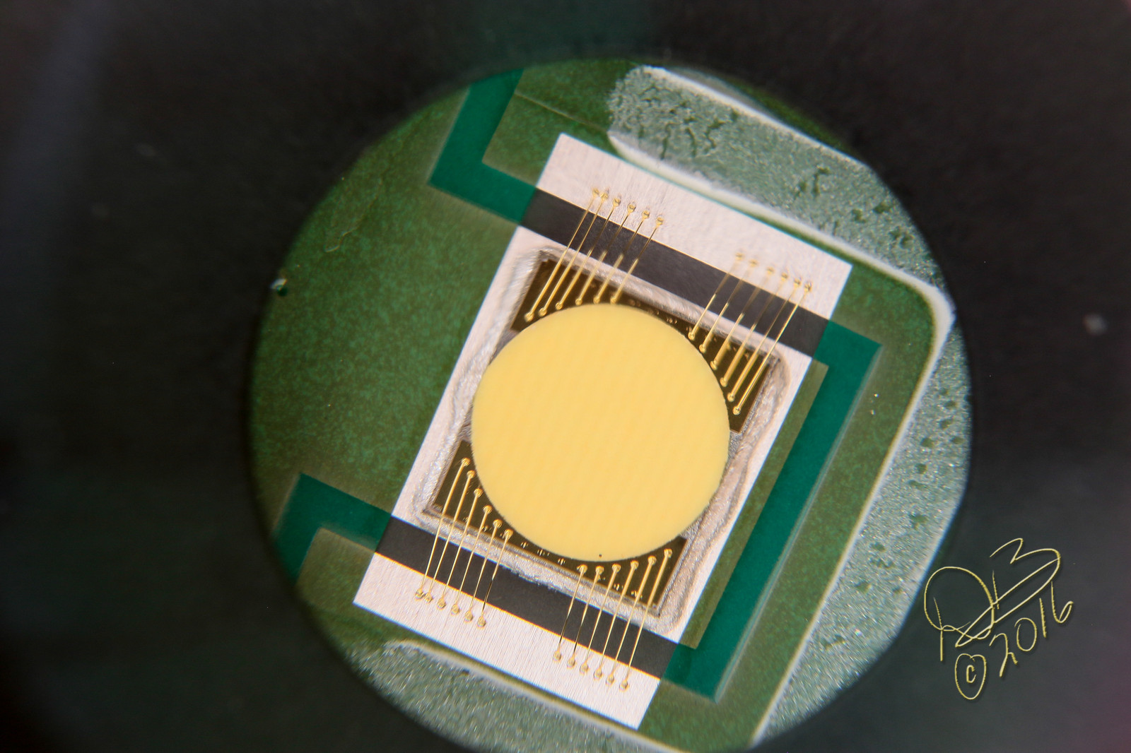
I removed the AR coated window and it’s metal frame from the SBT-70. I like the look of it better and it seems to have a bit cleaner beam profile without that extra piece of glass between the phosphor and aspheric. ![]()
Got a chance to put mine together tonight. Overall I’m very pleased. Its a 4000K MT-G2 with an LD2 driver. I think this big emitter looks great in there:

The overall light is a great size, smaller than I expected for a 2x26650:

Yes its got that hexagonal beam profile when zoomed in:

I’ll try to get some real outdoor beamshots later when it gets dark.
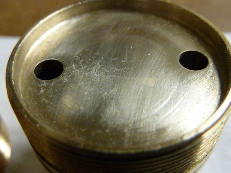
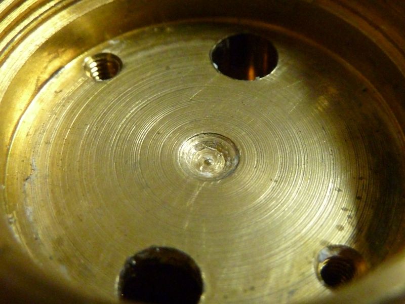
I do have one gripe/complaint. The machining on the brass pill was pretty rough, especially on the surface where the mcpcb goes. I know many of them from all sorts of manufacturers show the machining rings, but this one was even still domed up in the middle, like a very shallow cone. My mcpcb just rocked back and forth up there.

Took about an hour of sanding to knock it down flat, but the final results came out very well. The mcpcb sat down like its supposed to and the black cover piece fits like a glove.


Beautemous! ![]()
Anyone else ever have one of those days modding that nothing seems to work and/or work in reverse of the plan? Today was one of those. I attempted to put an LD-2 in the Z1 in order to have the current lowered to 12A and regulated. No worky. I couldn’t change modes, Turbo only. So I tried again, a second LD-2 this time a little more painstakingly modified with the required components. I got modes, but it was a chore to actually make them change.
I finally decided to re-install the FET+1 and use smaller leads to tone it down a bit. This is sound logic, right? Going from 18ga leads to 20ga leads should throttle the draw at least a little, right? Well, not today. I went from 17.97A to 18.75A with the smaller leads.
![]()
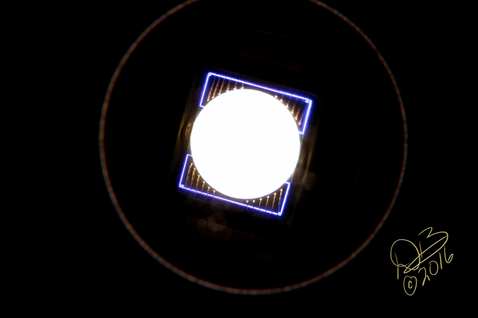
Those MTG2 LEDs look beautiful even when off
Dale I hope you have a lot of that magic wire ![]()
+1 and Amen !!! :+1: …. ![]()
Miller, I think what happened is that a total rebuild ended up giving me better ground contacts such that even the slightly smaller wire’s yielded higher current. Considering the first build was purely off the cuff, the second, third and fourth likely taught me something. ![]()
[built it with the FET+1, rebuilt it with the LD-2, then tried another LD-2, then put the FET+1 back in. This is a piggybacked driver set-up, so each revision took a complete tear down and rebuild.]
Good input.
If Sharpie does not report on this in a day I will contact Paul and check it out.
The brass pill in both my Z1 and X1 were done very well. So perhaps they had a rough one slip through?
Edit: Finding that I can keep the Z1 to reasonable current levels with the FET+1 in place by choosing an appropriate cell. While the dark purple Efest 4200mAh cell yields preposterous current, a MNKE 26650 yields a more reasonable ~10-11A (9A with a low charge, charging now to see what a full cell actually does) A Samsung 26F 18650 will do around 8-9A, so it’s feasible to use a proper low discharge cell to run the SBT-70 at lower levels.
I really like that MTG build, and if I decide to go multicell, that’s what I’ll probably use. I still have a bunch of them from when they first came out.
I have already drawn Jaxman’s attention to this.
Please give him time to respond.
I have to believe they know there’s at least a slight issue there since the assembly video they provided showed taking a knife of some sort and scraping that surface smooth before assembly. That would help to remove some of the ridges I guess but it wouldn’t help reprofile the surface to remove the dome/conical shape mine had. My noctigon literally rocked back and forth like it was perched on a fulcrum, because it was.
I mean these are mass-produced parts and at some point you have to call it “good enough” and put it into production, and at these prices nobody should expect perfection, but I would hope their intention is that most of them turn out better than mine did. And Dale said his was fine. It would be helpful to hear from others on this issue.
Thank god we’re modders. These are just the usual everyday things for us to overcome and correct. We’re up to it.
I thought that’s what the guy was doing in the video. Maybe I misunderstood him. I think I’ve been very fair to Jaxman in my two posts about this issue, stating that while it wasn’t ideal, it really wasn’t hard for me to rectify it and I can understand why any mass-produced product is going to have some small issues. If I’ve come across as anything less than helpful and understanding it wasn’t my intention.
Mine were both smooth while I always emory sand or file regardless. I do believe they (Jaxman) are being meticulous to make certain these are all done right. That is the purpose of this trial run. Very optimistic about this. I did try and purchase more parts and was asked to please wait until everything was in order first. That is also a very good sign.
Those machine marks on the pill surface look severe, worse than usual. I sand down pretty much every pill top of every mod I've done - been doing those for 3+ years. I'll check the flatness of the surface with a small straight metal edge - it's usually evident when you find it not flat. Many come this way - it's a function of the lathe/machining, and them not taking the time and care to get the surface smooth and flat as it should be. I'll start with as low as 240 GRIT and work my way up to 2000, or even 2500 GRIT. I cut the sandpaper into think strips and use them wrapped over the hammer end of a punch - it's pretty flat and smooth, so seems to work well.
This is (or was) pretty common practice for us modders on BLF for a long time, but not everyone does it. You want the two surfaces of the MCPCB and pill top to bond as best as you can metal to metal, then the thermal grease simply fills the micro scratches/trenches on the surface. That's the idea, but we are not always dealing with smooth flat pill tops unfortunately, usually they bump up in the middle, but the sanding can eliminate most of the bump.
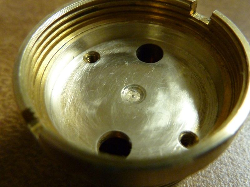
Also a tell tale sign of a poor quality pill top is presence of lots of thermal grease, or if there isn't much used, only spots of it are present - indicates the surface is not smooth so it didn't spread under pressure. This is an example of a brass pill after sanding:
Here's a good before/after of a XinTD C8:
I always do mine too. I started with 200 grit on this one and ended at 1200, which was the finest I had available. I should’ve taken an “after” photo of mine before putting it together, but I didn’t. Here’s a before/after on a Convoy S2+ pill heatsink though:
Those are easy because you can just lay the paper on a smooth surface and go to work. These pills with the raised lips are a lot harder to do, obviously. The nail punch is a good idea. I’ve been using something similar - a 1/4” drive extension with the paper wrapped around the solid end where the socket goes.
I thought we were just having a discussion here, maybe getting (somewhat) off-topic, but not terribly. I didn’t see much speculating going on, at least not since I made an assumption on what the guy in the video was doing that may have been off the mark.
No more posts on scabbier pills, no more posts at all - don't like your tone, yet another Rude, so I'll mark it as such, and not participate in this thread anymore. I've about had it with this treatment, and seeing others treated the same way, when all I'm trying to do is be helpful.
