Exactly - I’m almost certain that’s not the perfect sensor to use, but the idea may have merit for someone more clever on this than me.
Looks awesome djozz! What firmware are you using on the driver and where does the bleeder go? Did you put the bleeder on C1?
I first tried it without bleeder and that messed up the user interface bigtime. I had soldered the driver in thoroughly to heatsink the 7135 chips (they have to burn up almost 2V overhead voltage in red led flashlights), so the bleeder on the led side of the driver was no option anymore. I had soldered the 4th star of the (stock firmware) Qlite to ground (mode group 4) and that trace goes quite far to the middle, with scratching off some solder mask I could solder a 0805 resistor from that trace to the central batt+ pad
I’ve ran into this project in a thread here, and it looks like it could be adapted for tailcap. In a nutshell, guy is running Luxeon Z from CR2032 with more than a year of runtime (26.3 μA draw), for the same reasons as us. I will try to make more sense of it, all of the source is available.
That’s an interesting idea. How would a low sensor reading trigger LED activation?
I’m wondering because an attiny13 could do it, but… the ADC parts of the chip use more power than simply leaving the LED on all the time at a low level. I guess it could keep everything off most of the time though, waking up once per second to take a reading and then go back to sleep.
I wonder if it’s possible to get the light sensor and tail LEDs in different frequencies so the LEDs won’t make it think it’s in a bright place.
Where did ya get that triple nichia 219b red emitter ? ![]()
Havent even found triple red ….


I bought them at Lumitronics ( leds.de ). But I tested them a bit under the performance of the red XP-E2.
Hi pilotdog68, could you possibly do a version of rev5.1 for 14mm boots that uses (4) 1206 LEDs and only (1) resistor on the back? If there isn’t room to do 1206 LEDs, could you do 0805 LEDs instead?
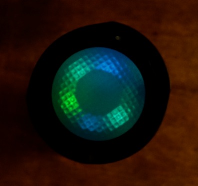
Today I made a S2+ 18500 shorty with illuminated tailcap. (some more details perhaps tomorrow in the what did you mod today thread)
driver: Qlite revA with Nlite firmware (from MtnE)
bleeder: 470 Ohm
ledboard: pilotdog68’s dumb 16mm 6-led ring with a resistor for 3 times two pairs
leds: from a bag with random blue/cyan/green mix 0603-size from ebay
resistors before leds: 2 pairs of 6.7KOhm, 1 pair 1.8kOhm (tweeked)
current through tailcap: 131 micro-amp (so 1.8 year on a NCR18500A)
The light is well visible in the dark but not overly bright. The driver UI suffered somewhat from the lighted tail, every half-press gets you to low again, so you have to go through the cycle starting from low every time you change mode (not too annoying with 4 modes)
Hello friends. I order a few boards a while back and have just picked them up to attempt my first lighted Tailcap. I ordered 16mm and 14mm rev5 boards. The 16mm boards look fine, but am I missing something on the 14mm board? I can’t find the ground plane. The trace for the neg pad of the LEDs goes to the end of the board and it appears as if the board was cut short. I’m a little confused, please help.


You are absolutely right… They cut it way to short…
I think that’s the one I’ve used a bunch of without issues, so the problem isn’t in the file.
Contact Oshpark customer support. They are super fast to respond and will rush you replacements for free
Hmmm… I don’t know if that makes me feel better or not? :confounded: I thought I had to have been missing something so I looked at it for quite a while before I gave in and posted. Thanks for the help! I’ll contact oshpark. ![]()
I checked with oshpark and they believe it is a result of the copper layer being too close to the board outline. She says it must be 15mil or sometimes the mill with cut the wrong side of the line. IDK?
I want to try this little hack on Manker E14, I see that it’s already using custom board for the switch.
I have soldered 2 SMD (with code 103 and 104) resistors and 2 nichia LED as following, but it still doesn’t work. Do I need to add another resistor on the driver as well?

I know my soldering job is not great but I tested with my multi tester and they turned on.

Please advise.
The Manker E14 has the BLF-A6 driver, but a (bleeder)resistor must be added, try 470 Ohm between batt+ and ground (one way to do that is from the led+ wire-pad to the outer ring).
I have wanted to try this for some time, I love it on the X5. The issue is reading all 1140 posts to see where exactly things stand.
Is the OP updated with the latest developments?
Also which boards should I order, there are so many options and it doesn’t make a lot of sense as to which one you should actually order without the background on why there are so many.
I basically want the most universal setup that can be used in the widest possible number of lights and be reliable. It also still need to offer high current carrying capability to the switch.
Pots are nice but not a must.
I would be using it in S2 tube lights mostly and other lights with similar sized tailcaps.
Thanks djozz, I have made it glow.
Just need to tweak the R size to get my desire brightness.
Are you using that green tailcap in the picture? My thought is that they might be turning on in the flashlight, but so faintly that it can’t be seen through the green. Adding the bleeder to the driver might help.
I’m not up on my resistor codes. What are those values on the tailcap? (103 and 104)
edit: just saw your new post. glad it is working. It definitely takes a lot of playing with values, with is why some started using pots