What did you mod today?

I had the same behavior on a triple 219C with the same banggood driver you had (used the Kronos X6 driver).

I’m not an expert, but what I saw was that too many amps caused it to shut off in the highest modes. The low vf of the 219C means that it’ll suck up lots of amps. I think I read that XP-G3s also have a low vf. If I used a regular NCRB, I could go to the high mode no problem. High drain cells just made it blink and shut off. Strobe mode wouldn’t work either.

I swapped it to an A6 driver, and it works fine.

I reused the driver with a triple XP-L and it just barely is under the amp threshold to cause the high mode to function. If I try to take a tail reading with my clamp meter, high mode doesn’t work because the low resistance of wire. But high mode works with the tailcap due to the added resistance. I think 14+ amps causes that banggood X5/X6 driver to act funky.

RMM said his driver wouldn’t have that problem due to better parts and layout.

I’ve been working on a mod for a few days and it seems that it can’t decide wether it’s a success or a fail. Is it possible for a flashlight to contract the ZiK virus and shrink its brain?

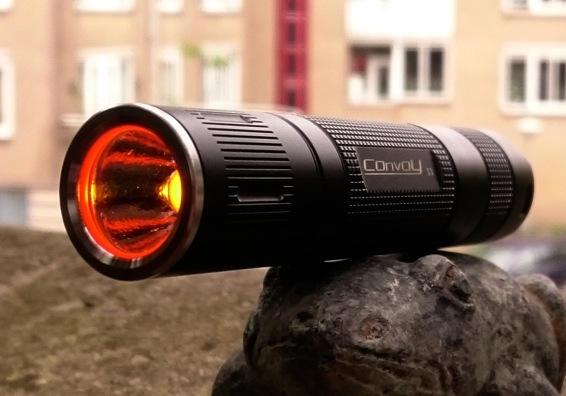
It all started out to be an RGBA using a board with four Luxeon Z. Unfortunately, the board that came with the four coloured emitters was square, so I had to grind it to fit a Convoy S2+.
Ahhh. There goes that stupid ouchyfoot again, always trying to fit a square board into a round hole.

I figured I’d grind and drill blank board, and then reflow the emitters from one board to the other.

I won’t do that again!

These little Luxeon Zs only like to be mounted once, at least on a multi board. I’ve done these boards before using a new board and new emitters with solder paste and everything snaps nicely into place. Taking them off one board and transferring them to another is a horror. They only have two pads with a hair between them, that goes for the board as well. Removing them, some pads retain solder, some come up bare, so more paste must be used.
The old solder doesn’t want to flow, and excess just spreads to fill the gaps between the pads, or attaches itself onto the neighboring emitter. Trying to shift them around just makes matters worse. The next thing you know, all four emitters are attached to each other all cockeyed. The more you work to fix it, the worse it gets. Finally the emitter pads are all clarted up with solder in one big shorted mass. Not to mention the ones that get tipped ove into the hot solder.
After an hour of work and six ruined emitters I said “to hell with this”. I went from RGBA to RGBR/O to RGBW.

Three deep breaths. I heated the board for the hundredth time and wiped off all the solder with a damp Brillo pad. Fresh start. Four new emitters. RGBW. All working.

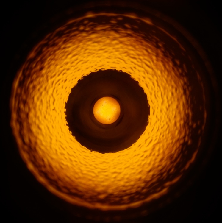
One of the main reasons I wanted to build this light was to test that waffled optic. One of the main faults with multi die emitters that work independently in a reflector light is that because they are all offset, the beam profile looks like a donut with a bight out of one side. I was hoping this type of optic would even that profile out, and it does. I just thought I’d mention that now in case I lose my train of thought with my woebegone whining.

Standard RGBW driver. I didn’t bother changing the wires because it’ll only be driving one emitter at a time @ 700mA

I sanded and glued down a plastic ring to keep the optic centered.

Sure, it looks sweet, but there’s something wrong with its brain and I can’t figure it out.
((more whining to come after these messages)

Now the problem is that it cycles through all the modes W-R-G-B-police strobes etc just fine. Once, sometimes twice. The next time it skips the strobes and goes to white. Then it goes from white to red to white, sometimes a green shows up, the back to white then only white.

If I set it down for five minutes it works fine, then gets all mixed up again until I only get white. I’ve resoldered all the wires. (Cheap melting Chinese wire), beefed up the ground, but nothing works. It’s sporadic.

I’m in. :slight_smile:

I don’t know anything at all about this kind of driver, but it seems like the MCU is getting hot or one of the Capacitors is. The emitters are working, the chips are working, the problem only starts when it heats up, so there’s something in the voltage to the MCU or the heat, which might be coming from the chips getting hot reducing 4.2V to 350mA. Sink the chips, see if that does it…

I don’t know exactly Ouchy, I have done several mods with this driver, even experimented succesfully with different resistor values and FET’s, but they kept working fine. Two observations that do give a clue perhaps what is happening, but may not get you to a solution:
*the driver is very sensitive to a lighted tailcap I found: I even tried without bleeder and with several bleeder resistor values, it all messed up the UI. So what is happening in the tail easily influences the driver timing. Did you do a spring by-pass, then try the flashlight without it, it may just improve. Try a lower drain battery, or higher.
*when the light is off, it resets to ‘start with white’ . In this driver this reset is fast, like 0.5 seconds. It sounds like perhaps that has become shorter than 0.5 seconds in your case. Try very short taps to change modes to try this idea out.

I though about the tailcap, and swapped out the back end from different S2s. I don’t think it’s the driver. There’s something else going on here.

I reheated a wiped the board so many times trying to reflow, that perhaps I ruined the integrity of one or more pads and the solder adhesion is iffy. Also. I ground down this board and drilled holes through the traces. Something could be moving once it gets hot causing some kind of short. Although the board isn’t DTP, it’s pretty nice. The entire surface is copper that is divided into eighths from the center out.
Wires? Who knows. If gone around and resoldered everything until all the cheap casings are melting into blobs. Still can’t be sure about the integrity of the pads.
Who knows, maybe the the AA isn’t cured completely and is causing a short. I removed the centering ring because it was sliding around and not curing to the mask.

I tried it a few minutes ago and it went through 8-10 cycles before it started glitching. Maybe it’s getting better. What if I wake up tomorrow to find it was all a dream and it works fine.

If it doesn’t get fixed I won’t have much choice but to scrape the whole board off and replace it with a standard RGBW emitter and board.

Did I mention that the optic is really good for these emitters?

Here’s what it looks like when it’s working.

Nice mod Ouchy. I like how you used the red, green and blue body pieces to go with your RGB emitter. :smiley:

Where’d you get the optic?

I had a triple with individually addressable leds (same RGBW driver as Ouchyfoot used above but modified, and not using RGB leds, link) with one of the leds a Pro-Light PC-amber one at ~5.5 lumen. On holidays when camping, or otherwise away from home with the family, I have used it as a night light for my son because he is afraid in total dark, it runs for 11 hours per night. But I like using it as my EDC as well, so it bothered me that I could not use it when he is asleep. So tonight I made a new flashlight with this led especially as his night light. The requirements: a ~5 lumen setting, safe, reliable, good runtime. I used:

*a Convoy S3 host I had around for ages and never felt much love for,

*a ProLight PK2N PC-amber led,

*a BLF-A6 driver (the led has such a high voltage that direct drive on a 18650 it still draws well under 2A),

*and did 2 spring bypasses to at least get some light out of it on high setting (for my own pleasure, the night light mode is only 30mA).

Because of the high voltage of the led, mode 4,5,6 and seven have close to the same output, but mode 2 is a nice 3 lumen setting for night light use (mode 3 is 30 lumen, a bit too much). I run it on a protected NCR18650B for good runtime, the 30mA/3lumen night light mode runs for 110 hours, with the light being on all night for eleven hours, this means 10 nights on a battery. The highest setting is 1.13A/190lumen.

edit: I pimped the light a bit with a red tail cap and a red o-ring, and I must admit that despite it being a Convoy S3 it looks alright now:

Thanks, I think. It would be nicer if it worked.

I got the optics from kiriba-ru, but only because I was ordering heatsinks from him anyway. You can get them in most of the usual places, mouser, Luxeon star, etc. they’re pretty common. I think they might also be nice with hi CRI nichias.

This morning I ripped apart my RGBW that I built yesterday ( Post #1150) to find out why the light keeps losing modes after it’s been running.

Today I removed the driver and unsolder end all the wires. Went over the edges of the mcpcb with an emory board where I had filed it down and drilled holes through the traces to make sure there weren’t any minute bits that were shorting as the board heated up and expanded. I cleaned up and tested all the pads and rewired everything with 30AWG Teflon wire.

At first it seems fine. I can run through all the modes a few dozen times until it warms up and starts skipping modes. This driver is extremely sensitive, barely touching the switch to change modes. I’m talking barely making contact.

At first it starts skipping the last modes, police strobes etc. then it loses blue, then green until all that’s left is red and white. Finally it loses red. If I let it sit for a minute, all modes are functioning again normally.

It’s not the board.
It’s not the wiring. This is proven by my DMM and the fact that everything does work.
It’s not poorly connected emitter pads that loose connection as the board warms up, as I can turn it onto blue, one of the first modes that goes, and leave it on for twenty minutes. After leaving on this mode for some time and try to cycle, I only get white again.

Therefor, it must be the driver.
This driver was designed for multi die RGBW MC-E emitters. I have one exactly like it in another light driving an MC-E with no problems, so now I don’t know if the driver is defective, or if there is something about the voltage requirements of these Luxeon Z emitters that is confusing the hell out of it, causing it to warm up and start losing modes one at a time.
That’s about as far as my knowledge will take me on this issue…

How’s the switch?

(just beat me to it)

Switch?

Switch is good. It’s an S2+, so I’ve even swapped the rear ends of three others onto it to test. Same result. This driver is ultra sensitive to a barely touched press. Forget about soft press, this driver likes to change modes by the least amount of touch the switch allows.

I had something similar happen that drove me nuts, eventually i did pin it down to the switch, the switch had worn just enough that the pressure of the rubber boot was ever so just enough to press in the button to cause most of what your describing.

i added another plastic spacer/washer giving the button more breathing room and everything worked perfectly since then.

I tried four switches, all brand new. One S2 metal boot, two S2 rubber boot, and one non convoy fwd. clicky. I’m not worried about the sensitivity, I’m more concerned about why it keeps losing modes one at a time until there is just white left.
I’m really starting to think that there is something about those Luxeon Z emitters that this driver reacts to.

Can you reflow the Luxeon Z off and swap in a color MCE? If you have one and if they are the same footprint? If it works right with MCE then the problem would be confirmed to be the Luxeon emitter.

If the footprint is different, you could try an MCE on an MCE star. If it worked that would confirm that the problem is with the Luxeon emitter or star.

No. Can’t just swap emitters. The luxeons are four small separate emitters, each with their own footprint. I do have an extra MCE mounted on its own board, but I have to await a renewed driving force before I can tear this one apart again.

A dirt cheap SkyWolfEye (don’t bother)
1-mode 1xAA-2xAA driver and an old amber XPE emitter
for use with a “4/3AF” NiMH cell, to give to a friend who already has several such for nighttime winter use, way off-grid.

Old school, an SP-98 Sipik clone with a swirly multi tone blue/lightblue/white pattern either painted on it or wrapped. My friend wanted more out of it, so I stuffed a 1/2” thick copper plug in the hollow pill, glued it in with Arctic Alumina Thermal Adhesive, used a 20 to 17 brass adapter ring to mount a 17mm FET+1 driver with A6 firmware. Swapped in an XP-L HI emitter on a 20mm Noctigon.

Pretty bright! The square image shows the oddly patterned XP-L HI die quite well, not sure if I should have done something different there, might pull it and put a domed XM-L2 U4 1A in it’s place.