djozz driver hack #2. (was: Colour driver build, based on D882 sot89 transistor?)

The gate input to a FET acts much like a capacitor. It is sensitive to voltage and does not draw much current at all except whwn the drive signal is changing.

A bipolar transistor input acts much like a LED/diode and is driven by current… hence the need for current limiting resistors.

ding ding ding :slight_smile:

Oh and apologies…I totally forgot the RGBW mastah tterev3

...necro-ing an old thread of mine....

...and renaming it :-)

1.5 years ago I suggested using the set-up of the intl-outdoor RGBW driver for a new BLF driver design. I can't do electronics, I can't do software, I only know Ohm's law and have a veague idea what a transistor does and a FET, so I hoped that it was picked up by someone. Well, no one did so I did some hacking of the driver myself today and was quite succesful sofar. Perhaps this raises interest after all to do something with this driver?

What did I do?

*There's 4 channels, the stock user interface starts with channel 1, half press for channel 2, half press for channel 3, half press for channel 4, en then some uninteresting blinky modes.

*Each of the 4 channels is regulated by a transistor that is directed by the MCU for on/off and a resistor between MCU and transistor for the amount of current (stock resistor is 911 Ohm, for a current of about 700mA for each channel, the exact current is a bit dependent on the type of led).

*For channel 1, 2 and 4 I tweaked the resistors: 39kOhm for channel 1, 4K7 Ohm for channel 2, 39kOhm for channel 4

*On channel 3 I removed the transistor and replaced it with a FET (I had a small N-channel FET that I got from Cereal_Killer in a distant past). I also halved the stock resistor to 455 Ohm by soldering a 911Ohm on top (for historical reason, the FET also worked on 911Ohm). I have no idea what a FET needs and what comes out of the MCU, but it just worked

*I made a triple with a XP-L Hi 7A1 led, an Oslon SSL80 4500K 96CRI led, and a Prolight Opto PK2N pc-amber led.

*I connected channel 1 and channel 3 to the XP-L, channel 2 to the SSL80, and channel 4 to the pc-amber led.

*I got the following currents on a purple Efest 14500 cell: channel 1 ~30mA on the XP-L Hi, channel 2 220mA on the SSL80, channel 3 3.45A on the XP-L again, channel 4 ~30mA on the pc-amber led.

So the UI now is: start on XP-L low (estimate 10 lumen), half press for SSL80 medium (estimate 50 lumen), half press for XP-L high (estimate 600 lumen), half press for amber (estimate 5 lumen). And then some weird blinkies, but a slow half-press always brings back the first mode. I will know the outputs exactly when I have build this in a S2+ shorty sometime in the future. Every output is without PWM btw, and in the process of tweaking I was able to make a very low moon too, using 1MOhm.

I have no idea how this driver modded like this holds up in use in a flashlight, but I'm pretty surprised that everything I thought out worked just like that.

further progress in post #14

Replacing a transistor with a fet. You know far more than I. It sounds like your on the track to somewhere.

And still I have little clue what I’m doing electronically. If I read in the Attiny25 developement thread, apart from software things, how much electronical stuff needs adjusted all the time, I feel a bit lucky that this just seems to work.

And at least I’m on track to my ideal simple effective driver for a single led flashlight too, without having to do anything that I am not able to do (like programming/flashing MCU’s): 4 modes, no memory, each mode fully adjustable (by choosing components) from lowest moon to direct drive, each mode real current, no PWM.

I finished the mod with this driver!

The host is a Convoy S2+ with rubber boot (I like the rubber boot version better than the metal switch one, it looks nicer and the clicky feels better), in fact the host that came as the 365nm Nichia S2+ that was a good deal at Banggood a few weeks ago. I salvaged the UV-led for another test one of these days. I ordered separately two black shorty tubes from Simon, but today I found that the one tube that I had leftover from ReManG's group fitted the S2+, I just had to roughen up the threading on the head-side a bit to have it make electrical contact.

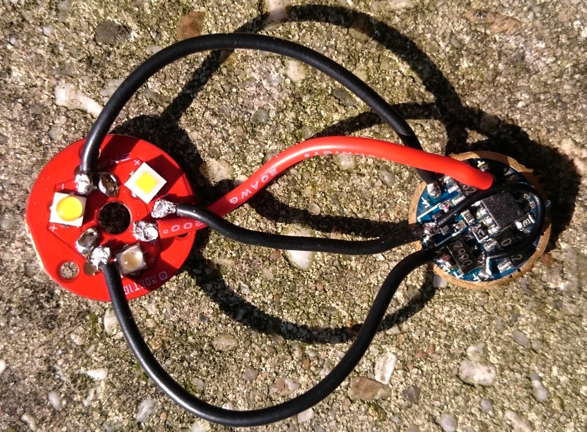
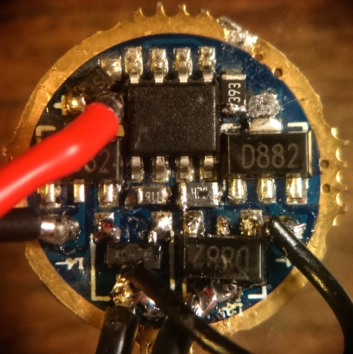
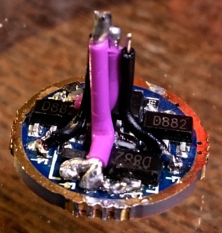
On the driver I changed the modes that I described above a bit (by relocating some wires and swapping a resistor on channel 4 from 39KOhm to 911 Ohm) to make the UI still more to my liking. Now the UI starts with 5lumen low on the amber led, then 60 lumen on the WW XP-L Hi, then 700 lumen on the XP-L Hi, last 160 lumen on the 96CRI 4500K SSL80 led. I ran out of 22AWG teflon wire, so I bought a new batch on ebay, from now on many mods will have purple wires! :-)

The mod is basically the same mod as the second red S2+ that I did lately, in short: it is a Convoy S2+ shorty that accomodates a 18500 battery, the extra space was created by using triple optics, triple Noctigon, drastically shortened pill by cutting off the led-shelf and much of the threading so that there's only just enough space inside for the driver, soldered a 1mm copper disc on top as a new led-shelf, soldered the triple Noctigon on top of that. The springs are intl-outdoor CU-Beryllium springs, but the one on the driver side was made smaller by cutting one complete turn off the wire. The glass lens was kept in place before the optic.

Of course not all modding went smoothly, everything had to be re-done at least once, and the worst what happened was that the driver seemed dead at a certain point, and I spent two hours trying to find the fault, gave up, tried again and found that the led+ pad was right next to the MCU and that it shorted to an invisible but apparently exposed pad under the chip :tired:

The netto result looks like this:

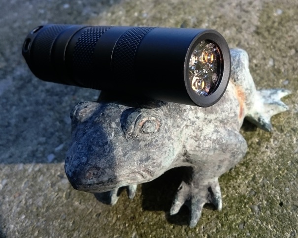
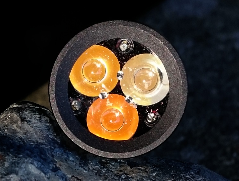
I'm really glad with the result! The UI is channel1->channel2->channel3->channel4->3boringblinkymodes. The blinkies would be annoying but because the driver resets after a pretty short half-long press (1 second) , from all modes you can directly get to start again. This is what's finally on the channels:

channel nr resistor value between MCU and transistor the led that is wired to this channel tail-current on a Sanyo 1700mAh 18500 output measured in integrating sphere runtime on a 1700mAh Sanyo 18500 battery
1 39 kOhm ProLight PK2N pc-amber 27 mA 5.5 lumen 2.5 days
2 4.7 kOhm XP-L HI U4 7A1 3000K 240 mA 68 lumen 7 hours
3 455 Ohm (transistor swapped with FET) XP-L HI U4 7A1 3000K 3.5 A 700 lumen 30 minutes
4 910 Ohm Oslon SSL80 4500K 96CRI 1.0 A 185 lumen 1.7 hours

So the 5.5 lumen low is now done by the pc-amber led, what feels right and is useful as a night-stand light, the x10 mode spacing to mid and to high is exactly what I like best (700 lumen in warm white :love: ), and the SSL80 96CRI led is good for seeing true colours if that is needed.

*The high setting is not sustainable, after a minute it gets too hot to hold.

*I do not like the beam of the XP-L HI through the Carclo very much, it is a bit square-ish. Works fine no problem, but it is not perfect.

*The SSL80 beam is a bit off-center, again fine but not a perfect beam. The led must have been reflowed just a bit off the center on the solder pads.

*all modes are true current without PWM, so the efficiency on the low modes is as good as it can be.

As a FYI, I tried a lighted tailcap with this driver (with warm white leds in the tail I would have a real moon-mode on top of the UI), soldered a 470 Ohm bleeder resistor and screwed on the lighted tailcap of my red S2+ to check. Well, it does not work, the reset time after switch-off gets really really short, so that any mode change attempt turns into a reset to channel1. So I called it a day and removed the bleeder again.

I have one more mod using this driver in the planning, with the four channels all on the same led, so not a triple. Resistor tweaking on channels 1-2-3 and a FET on channel 4, I think a LFPAK33 FET will swap right in too. The currents will be 6mA->60mA->600mA->direct drive.

Very cool modding! These are the kinds of things I think of but don’t often try. Although I’ve tried a few things but have been intimidated by writing up the process.

Very nice mod Djozz! I too really like the 3000K XPL HI, nice application here!.

Do you think soldering on potentiometers in place of the resistors would work?

I had been thinking about that too, it should work well because the path that the potmeter is in does not carry a lot of current.

I was also thinking that if you wanted all four, or three emitters running at the same current, say 1.9A, you could use just one trim pot soldered to one of the resistor pads with leads running back to the pads for the other resistors.

When you were trying various resistors, did you try it with no resistor and and just a bridged pad?

No I did not try that. These transistors are limited in their power rating (can’t remember what it was) and the way that they are connected, they are not, like 7135 chips, cooled by a pad directly connected to the ground ring. I think that maybe 1.5A is what they can handle at maximum (assuming that they burn off, say, 0.8V overvoltage with a fully charged battery). So for a high current channel a FET is needed, the next level can be provided by one of the transistors at 1-1.5A.

i realize the thread is over 3 years old, but do you still mod, and sell drivers? i would like to buy some.

Cereal_killer has not been seen on BLF for more than year now, but tterev3 is around, and he even has released some new drivers recently.

thank you, djozz, i will contact tterev3.

Here’s my driver info thread: Introducing the MELD-X RGBW(uv) flashlight driver!

For some reason I missed this thread entirely. There’s so much I don’t know about even the more simple to understand circuits but I enjoy seeing them futzed with like this. So the center pin/tab is led-, left pin(tab on top) is control pin(base), and right pin is ground. I wonder if an RC filter could be placed in the pwm trace to control the voltage on the base. A sort of D/A converter with the output range tuned to the resistance range of the transistor.

I don’t think there is pwm at all in this driver, just per channel a standard voltage/current coming from the MCU that in the firmware is either switched on or off. The resistor value in between MCU and transistor determines how much of the current/voltage reaches the gate of the transistor and so how much current goes from ground to led.
(but none of the electronics experts at BLF ever commented on this driver, so I could be wrong)

But soon this thread will loose relevance, the driver is only still for sale at Mtn now, and there’s currently just 15 pieces left, I doubt that Hank will be making more of them….

That could mean the value is simply set to 255/255 but if pwm were used then maybe some kind of D/A converter could be used to convert the pwm signal to a variable voltage. Moot point if the driver disappears as have many others.