Looking good Don. :+1:
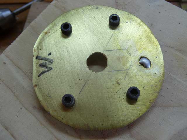
The cells need a contact plate for both ends. This is the plate that will service the bottom end which will be the positive + ends of the cells. I cut the plate from a strip of 2” wide, 0.010” brass. The raised contacts are brass 4-40 machine nuts. Soldering them in place was tricky as they kept sliding about. I used them as the design is to use some of the many flat top cells I have on hand. Heat damage to the oak scrap from using a butane torch for heat.
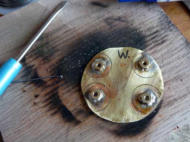
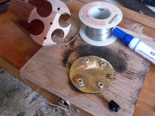
… another shot including the cell block. The W. denotes the section that covers the walnut wood segment.
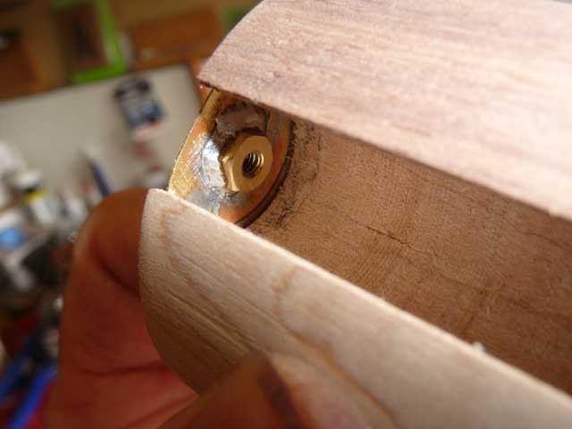
A view of the cell slot end with the plate held in trial placement.
More to come, thanks for looking.
You have literally gone nuts on this build. ![]()
:laughing: ![]()
I like where this build is going. :+1:
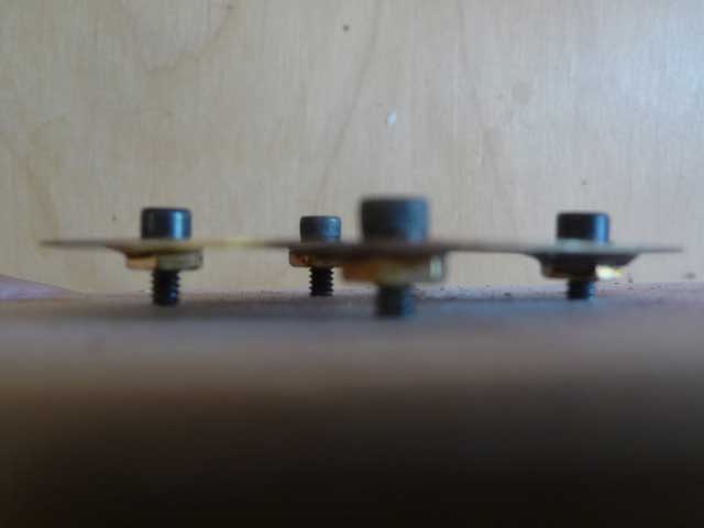
After dinner I headed back to the shop. It occurred to me there was a simple means to prevent those brass nuts from moving about when soldering. I drilled through the plate and threaded steel machine screws into the brass nuts. The black steel won’tstick with the solder. This helped retain the nuts when I heated for one more solder joint, to come.
Side / edge view of the brass plate, steel screws and brass nuts…
Hole drilled through brass plate center. A clearance hole. Tinned the brass with a little solder for the next step.
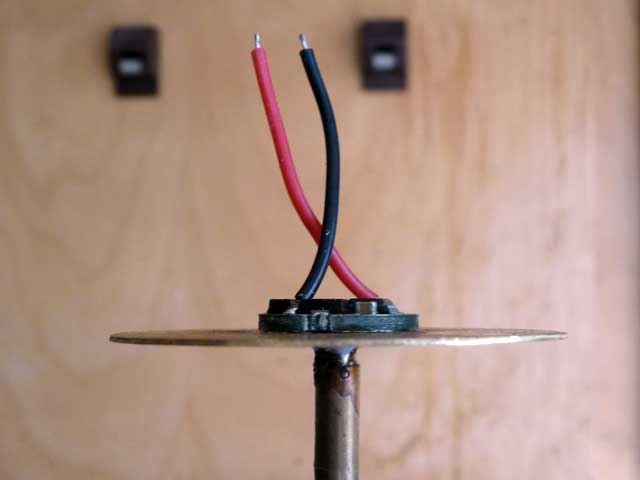
A small Omten reverse clicky switch is to be used…
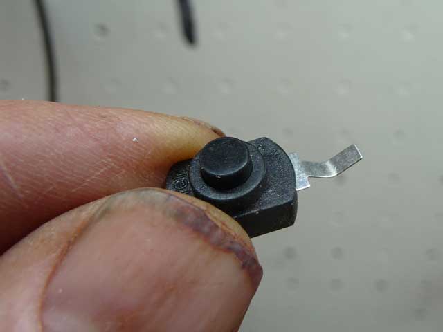
One switch contact gets soldered directly to the brass plate. The other end has a length of 18 ga. silicon insulated wire soldered to it.
I drilled through the center length of the cell block with a long 3/16” bit. This is for a wire.
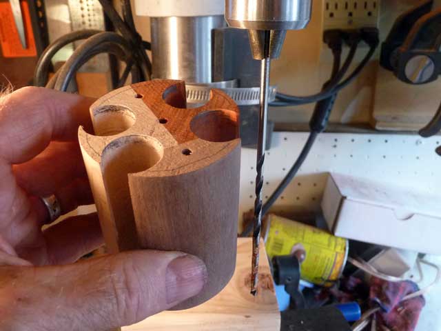
Drilled through and centered quite well where it exited the other end. As I was drilling the drill shavings were a nice mix of white and red.
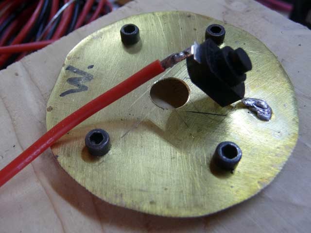
The wire is passed through the clearance hole in the brass plate. A double set of heat shrink tubing provides insulation. The four 4-40 machine screws will be removed before the plate and cell block is assembled.
Below is the view of what will be the bottom end of the cell block. Switch in place although I’ll likely use a small piece of 3M double sided tape between switch and brass plate. Or I could use cyanoacrylate, but that would make it more difficult to mod later.
Here’s the cell block with 4 x 18650 cells trial fitted. The cell block needs to be shortened a little, which will happen another day.
Thanks to all for the encouragement!! ![]()
Looking good, you thought of tapping screws before I could mention it.
This is looking great, Don! ![]()
Definitely getting interesting… ![]()
Very cool build. Can’t wait to see the finished product!
Great build! I’m looking forwards to more ![]()
This is so cool! Great job MtnDon, I just might have to attempt one of these
I like the look of your wood battery carrier. The remote phosphor strategy is neat too. It might even be more efficient than using a white LED and a separate diffusing optic since it accomplishes the two things at once. ![]()
I did some more this afternoon…
I needed a 9/16 hole on a sheet of brass stock to begin with. Brass is 0.020” thick. I clamped it between two pieces of wood and drilled.
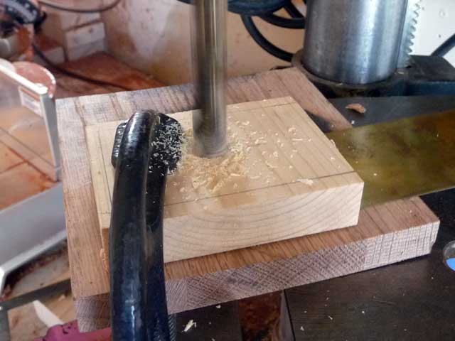
Here’s the result…
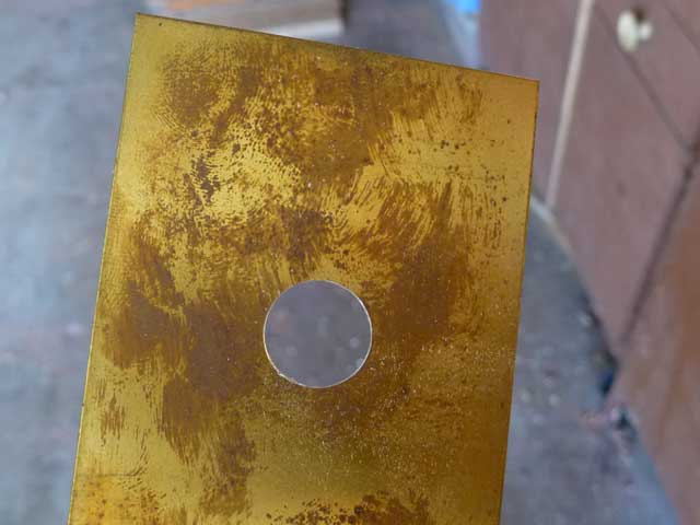
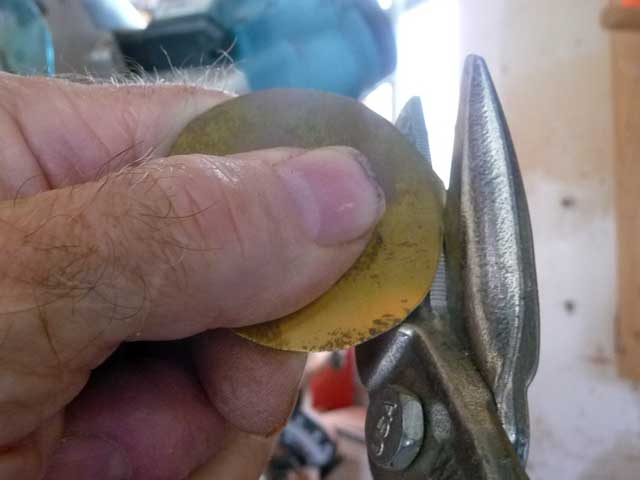
This is to be a round disc similar to the other one with the nuts soldered in place. So the snips came out again. And I did the self timer trick once again.
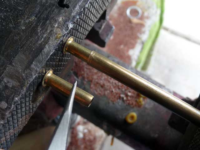
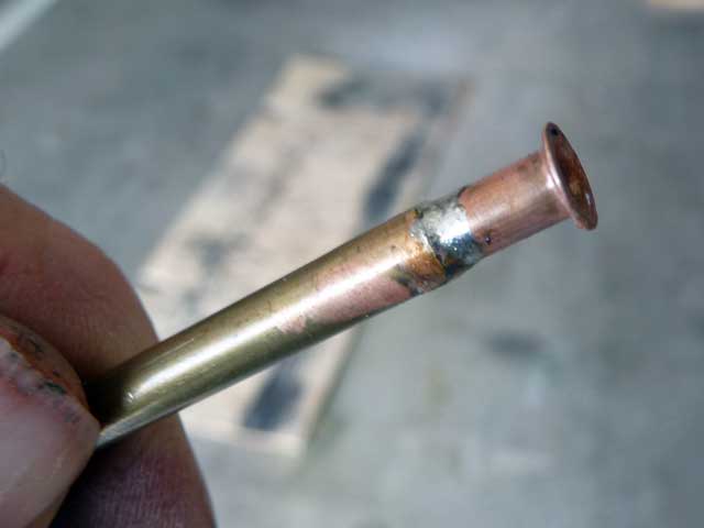
Alright… here’s a mystery part. ![]() The part being held with the tweezers is a plumbing part. Specifically a brass ferrule for use inside vinyl tubing with a compression fitting. I wanted to mate it to a section of brass tubing stock. The ferrule would almost slip inside the 3/16” OD brass tube. A squeeze with the vice did the trick.
The part being held with the tweezers is a plumbing part. Specifically a brass ferrule for use inside vinyl tubing with a compression fitting. I wanted to mate it to a section of brass tubing stock. The ferrule would almost slip inside the 3/16” OD brass tube. A squeeze with the vice did the trick.
Then some flux and some torch heat and solder gave me this… The brassiness of the plumbing part disappeared. I guess the flux cleaned it down to copper base.
Now I went and forgot to take a picture or two of some intermediate steps. ![]()
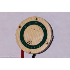
The driver I am using is a Nanjg-101-AK-A1. It is single sided. Here’s a stock photo I borrowed from mtnelectronics.
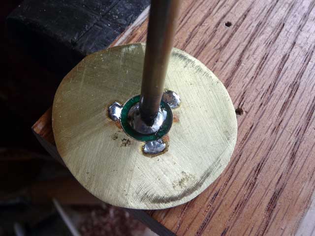
The plan/idea is to solder that brass tube and ferrule assembly to the driver + center. I used the ferrule to provide a flat and wider contact area with the center of the driver. The driver negative ring gets soldered to the brass plate. I filed three half round sections out of the inner hole I have drilled in the brass plate. I meant to show a photo… but got carried away.
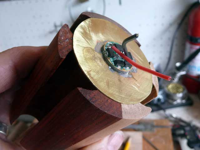
I tinned the side of the brass plate first. Then tinned the driver center and outer ring face. The next photo shows the tube already soldered in place as well as the three solder spots for the negative driver ring. As I was working I could see molten solder wick into place between the driver and the brass plate.
The driver is set temporarily into a drilled recess in the oak board with the electronics facing down. The brass plate carefully positioned over the smooth side of the driver.
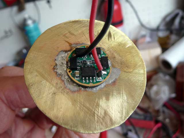
The view from the other side. Looks like a huge driver, eh! ( eh?…. I am a Canadian by birth, eh!)
Side or edge view of the assembly…
This is how it is to be fitted to the cell block.
I do think I will test wire the driver and led before I go further. That’ll be tomorrow’s first task.
This end will be facing up towards the LED and lid end that has already been shown.
I am waiting on some springs to arrive. They should be here in a few days time. The springs will be soldered to the underside of the brass plate.
That’s the zinc vaporizing from the surface leaving a thin trace of copper. Polish it and it will return to brass color. I’ve soldered drivers to many odd places. Hope you used electrical solder everywhere. I’m liking this a lot.
Nice plan coming together. :+1:
Thanks. Yes, electrical solder, real made in USA stuff from years and years ago when I stocked up when a local store went out of business.
Wow,creative design.
I am loving that wooden carrier, especially with three different woods together!