Definitely getting interesting… ![]()
Very cool build. Can’t wait to see the finished product!
Great build! I’m looking forwards to more ![]()
This is so cool! Great job MtnDon, I just might have to attempt one of these
I like the look of your wood battery carrier. The remote phosphor strategy is neat too. It might even be more efficient than using a white LED and a separate diffusing optic since it accomplishes the two things at once. ![]()
I did some more this afternoon…
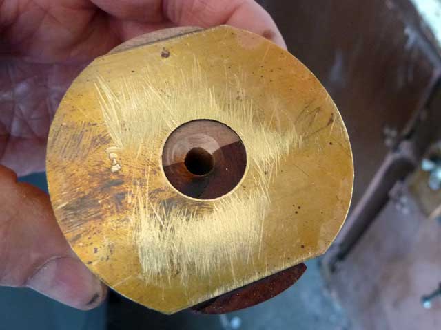
I needed a 9/16 hole on a sheet of brass stock to begin with. Brass is 0.020” thick. I clamped it between two pieces of wood and drilled.
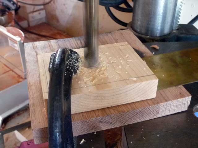
Here’s the result…
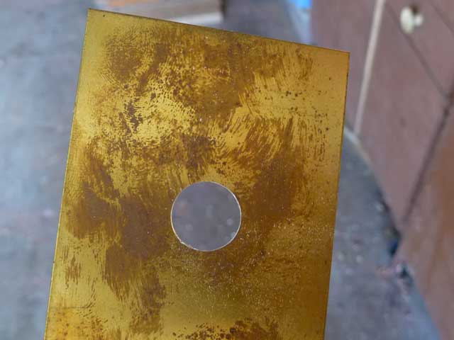
This is to be a round disc similar to the other one with the nuts soldered in place. So the snips came out again. And I did the self timer trick once again.
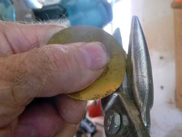
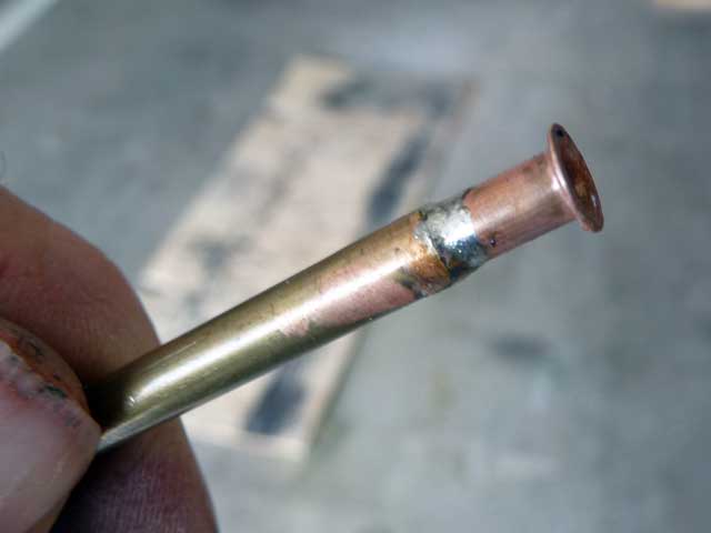
Alright… here’s a mystery part. ![]() The part being held with the tweezers is a plumbing part. Specifically a brass ferrule for use inside vinyl tubing with a compression fitting. I wanted to mate it to a section of brass tubing stock. The ferrule would almost slip inside the 3/16” OD brass tube. A squeeze with the vice did the trick.
The part being held with the tweezers is a plumbing part. Specifically a brass ferrule for use inside vinyl tubing with a compression fitting. I wanted to mate it to a section of brass tubing stock. The ferrule would almost slip inside the 3/16” OD brass tube. A squeeze with the vice did the trick.
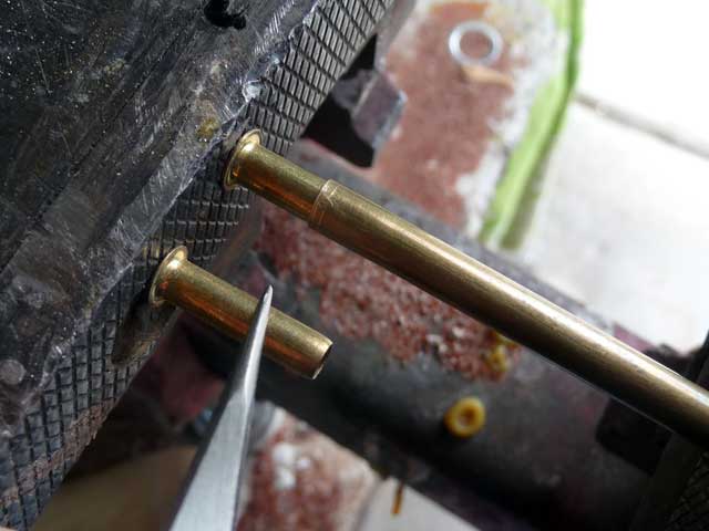
Then some flux and some torch heat and solder gave me this… The brassiness of the plumbing part disappeared. I guess the flux cleaned it down to copper base.
Now I went and forgot to take a picture or two of some intermediate steps. ![]()
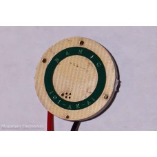
The driver I am using is a Nanjg-101-AK-A1. It is single sided. Here’s a stock photo I borrowed from mtnelectronics.
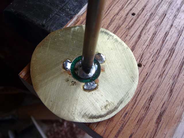
The plan/idea is to solder that brass tube and ferrule assembly to the driver + center. I used the ferrule to provide a flat and wider contact area with the center of the driver. The driver negative ring gets soldered to the brass plate. I filed three half round sections out of the inner hole I have drilled in the brass plate. I meant to show a photo… but got carried away.
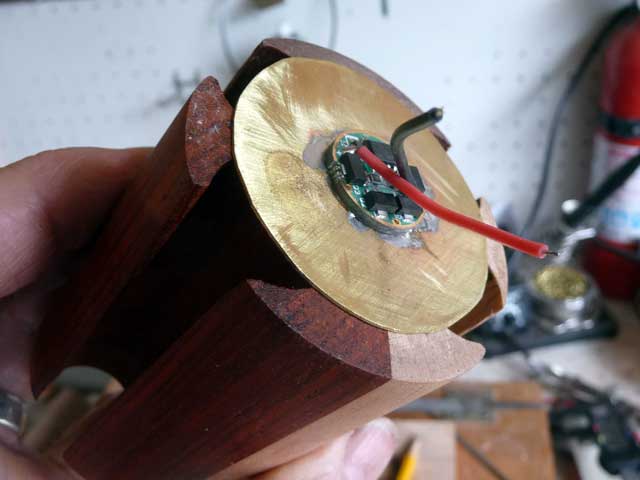
I tinned the side of the brass plate first. Then tinned the driver center and outer ring face. The next photo shows the tube already soldered in place as well as the three solder spots for the negative driver ring. As I was working I could see molten solder wick into place between the driver and the brass plate.
The driver is set temporarily into a drilled recess in the oak board with the electronics facing down. The brass plate carefully positioned over the smooth side of the driver.
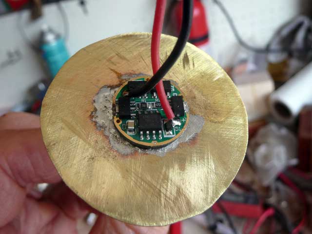
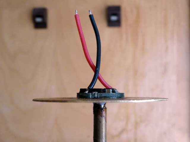
The view from the other side. Looks like a huge driver, eh! ( eh?…. I am a Canadian by birth, eh!)
Side or edge view of the assembly…
This is how it is to be fitted to the cell block.
I do think I will test wire the driver and led before I go further. That’ll be tomorrow’s first task.
This end will be facing up towards the LED and lid end that has already been shown.
I am waiting on some springs to arrive. They should be here in a few days time. The springs will be soldered to the underside of the brass plate.
That’s the zinc vaporizing from the surface leaving a thin trace of copper. Polish it and it will return to brass color. I’ve soldered drivers to many odd places. Hope you used electrical solder everywhere. I’m liking this a lot.
Nice plan coming together. :+1:
Thanks. Yes, electrical solder, real made in USA stuff from years and years ago when I stocked up when a local store went out of business.
Wow,creative design.
I am loving that wooden carrier, especially with three different woods together!
I tested all the circuitry, switch etc and discovered a small issue. RMM is a great guy and is bending over backwards to remedy the situation. Yet another excellent reason to buy stuff from him rather from Chinese sellers.
There will be a few days for me off this project as I need to return to more of the real life tasks that somehow keep getting in the way of this flashlight fun.
Ah - Bummer! I know how that real-life stuff is, though. It’s hard getting away from it, cause it always catches up with you eventually.
First time in here. Build is looking really good and you thread is very informative. ![]()
Living vicariously through all the other builds. Keep ’em going and keep me sane please. :confounded:
Some of you will readily relate to this… I have made a couple of changes to the project. The basic idea is the same but my execution of my idea has some changes.
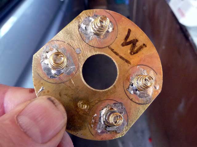
I re designed the upper contact plate that also has the driver mounted to it. Post #46 has photos of the first go ’round. The new plate is a little larger. The first plate was cut free hand with aviation snips. It had a somewhat irregular almost circular shape. The new plate is cut from 0.030” brass. I cut almost to the cut line with the snips. Then I mounted it in the vice with a wood backer and filed to the final shape. I think it looks better although functionally there is little if any difference
I soldered 4 springs I bought at mtnelectronics to the down facing side of the plate. I preheated the plate with a butane torch to tin the areas where the springs would be located. Then tinned the spring ends and positioned them. Light action with the torch brought the temperature to the point where the solder “flashed”. Coolong set the solder.
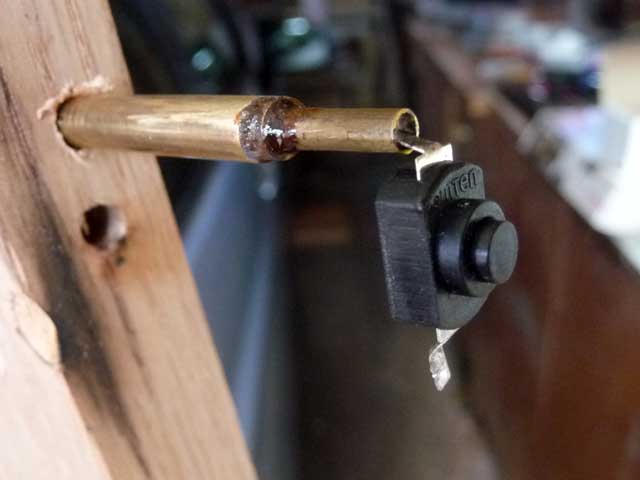
The Omten switch had a wire soldered to one terminal previously. That was back in post #37. I have changed that to be a brass tube. The brass tube will fit up the center of the cell block. There is a series of one tube inside another to get the diameter from smallest which fits the switch tab, up to the larger size. The other switch terminal will still be soldered to the lower contact plate as before. Here’s the new arrangement with a dual layer of heat shrink as insulation. Even though the hole through the bottom brass contact plate is oversize I figure this is some extra insurance in case something happens. (Heat shrink tubing not in this next photo but a subsequent photo will illustrate it).
Yet another change is to the upper end where the LED mounts. Previously I had a wood spacer ring. In part the spacer was there to drop the LED and remote phosphor lower. If the LED was mounted to the metal cap directly the mug jar top metal ring / band obscured the phosphor dome a little. I have replaced the wood spacer with an aluminum block.
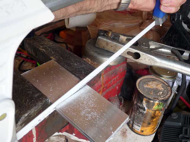
I calculated ½” to be a good thickness. Not wanting to drive over to the metal supermarket I decided to make a block from 2” wide x 1/8” thick aluminum strap material I had on hand. Four layers. Hand cut…
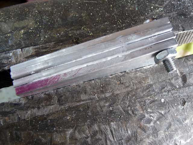
I used 10-32 machine screws to hold the alignment. Arctic Alumina adhesive was used between each layer. It seems to hold very well. Clamped in a vice waiting for the cure to complete.
I scribed the curved ends to match the shape of the cell block.

Then did a rough cut with the hacksaw.

That was followed with some use of a coarse bastard file.

Then a finer cut file… followed with some sandpaper. It is far from a perfect finish, but is hand made.
Drilled and tapped some holes. There are a couple of extra holes, one with a broken drill bit embedded in it.

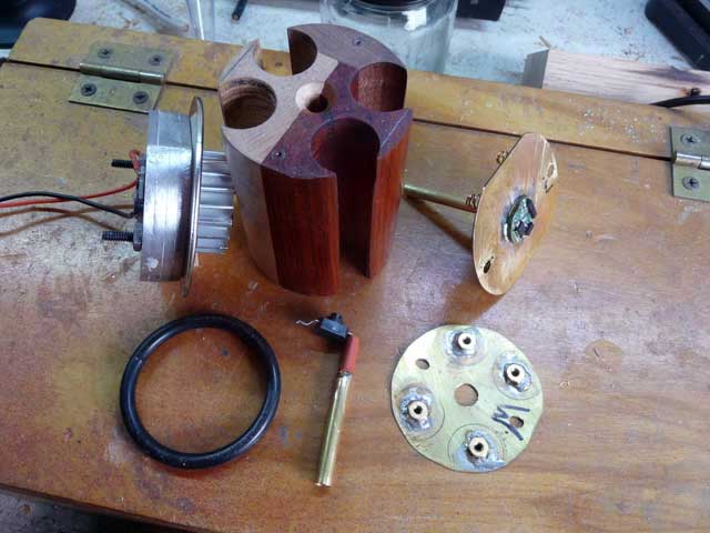
The aluminum block will mount to the underside of the metal mug sealing lid. The LED mounts to the lower face. The finned heatsink mounts to the upper surface of the sealing lid. I used Ceramique 2 heat transfer paste between the mating surfaces. Here are the major components, except for the mug itself. The assembled aluminum block, LED, sealing lid and heatsink can be seen leaning against the cell block. The switch brass post shows the heat shrink tubing.
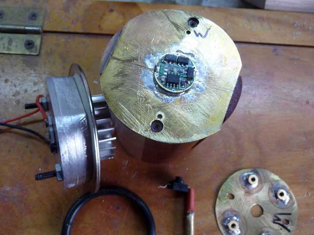
I’ll finish this set with a shot showing the new driver plate in position on the cell block upper end. The Nanjg driver is soldered over the center hole in the plate. The center contact (+) tube extends down through the cell block center to mate with the tube from the switch. One slides inside the other. My meter can’t read any discernable resistance difference between a single continuous length of brass tube and the section of one inside the other.
More to come…
All the woodwork this year is really awesome! I’m really liking the concept and design you’ve got going here, MtnDon.
What’s he doing now!!!
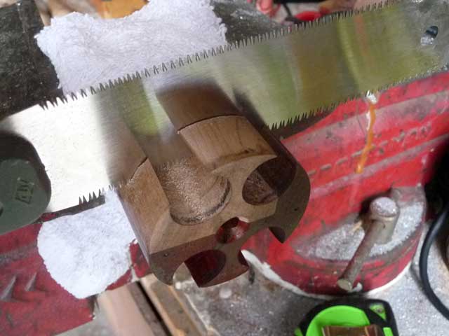
Never fear. This step was planned all along. Just never hinted at.
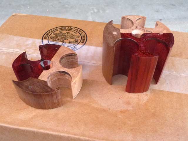
Now I have an upper section and a lower section to the cell block.
I think that is all for tonight. I gave the pieces a quick coat of clear spray to help keep the wood from showing all the handling. That needs to dry before the next step. I’m getting more excited!
More coming… thanks for following…
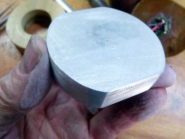
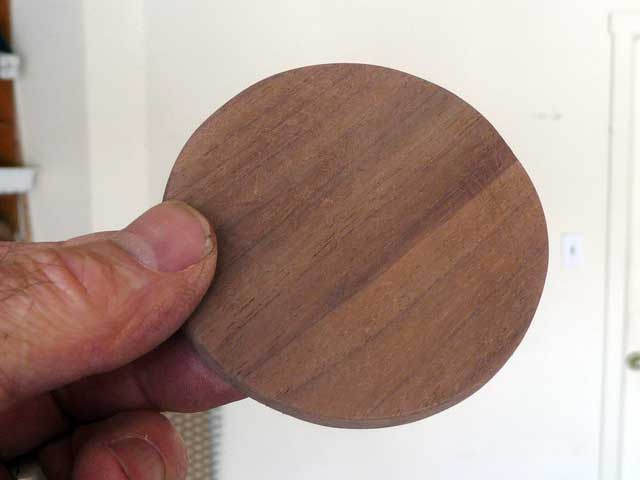
Did more work today on my project light. I had a small piece of bad luck and cracked the bottom of the mug. It is only acrylic. Unfortunately I could not find a polycarbonate or other better plastic mug. However all this meant was a change in design. I decided to make a walnut disc bottom from a 1/4 thick piece. Here’s the rough piece…

After filing with the coarse and finer files and some sanding I had a more or less round piece.
After some thinking and a little trial and error I came up with a repaired / modified bottom. I was excited and missed a few photo ops. Anyhow I did a trial fit of all the components and have a couple of photos to show. It is not wired up at all. I have to disassemble it and will then shoot some more detail shots. Here’s what it looks like (remote phosphor dome is not installed but it fits in the space made for it.)
Cheers!!! ![]()
![]()


For this trial fit I have only 2 cells in place. It will operate on a single cell or any number up to 4 once the wiring is completed.