Some of you will readily relate to this… I have made a couple of changes to the project. The basic idea is the same but my execution of my idea has some changes.
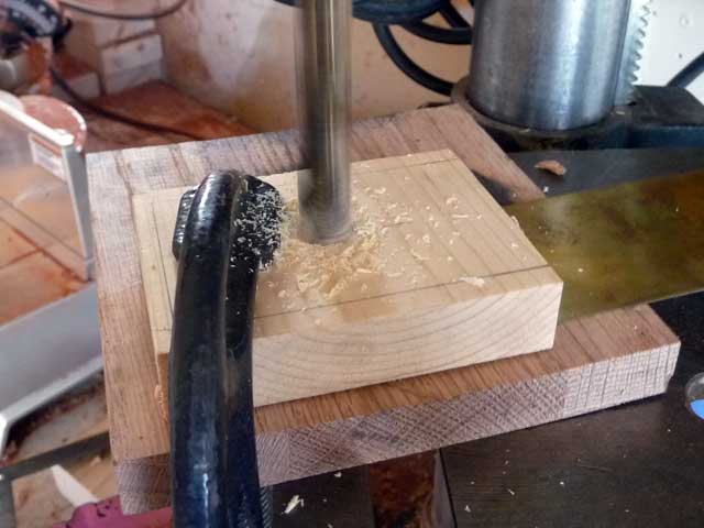
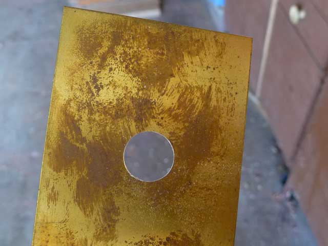
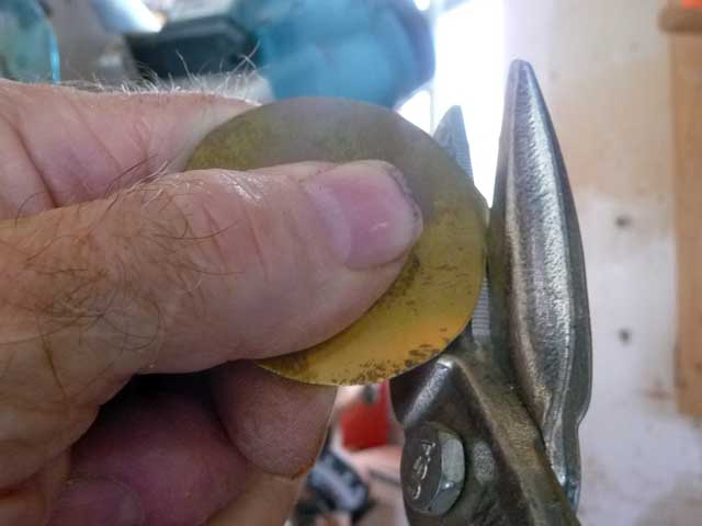
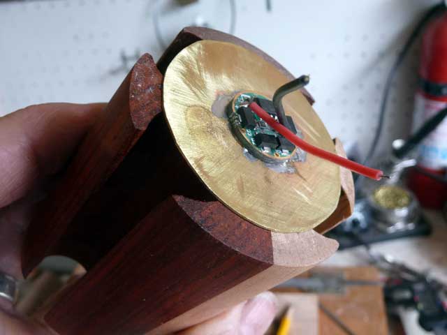
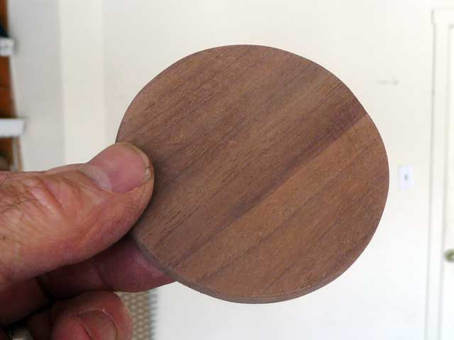
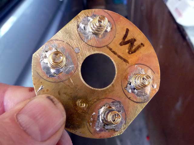
I re designed the upper contact plate that also has the driver mounted to it. Post #46 has photos of the first go ’round. The new plate is a little larger. The first plate was cut free hand with aviation snips. It had a somewhat irregular almost circular shape. The new plate is cut from 0.030” brass. I cut almost to the cut line with the snips. Then I mounted it in the vice with a wood backer and filed to the final shape. I think it looks better although functionally there is little if any difference
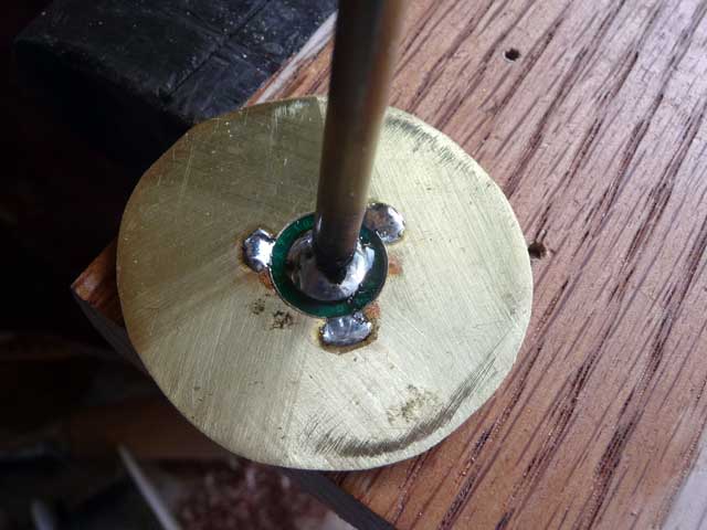
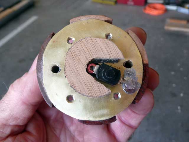
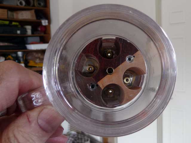
I soldered 4 springs I bought at mtnelectronics to the down facing side of the plate. I preheated the plate with a butane torch to tin the areas where the springs would be located. Then tinned the spring ends and positioned them. Light action with the torch brought the temperature to the point where the solder “flashed”. Coolong set the solder.
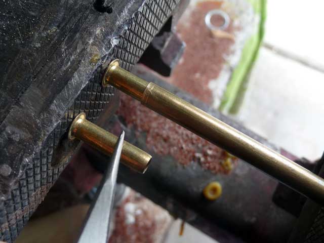
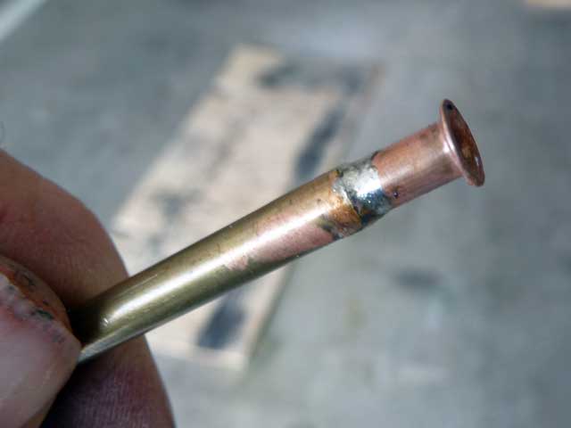
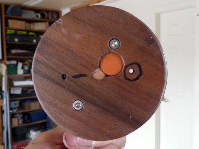
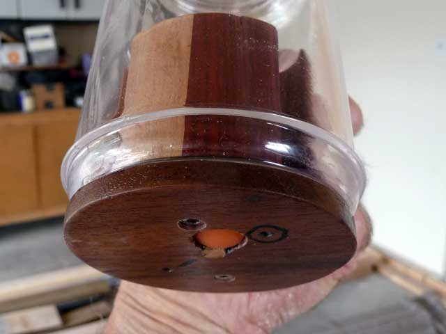
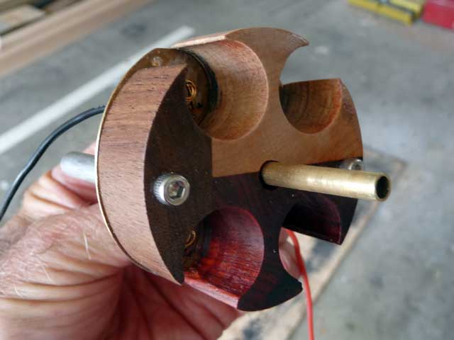
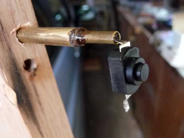
The Omten switch had a wire soldered to one terminal previously. That was back in post #37. I have changed that to be a brass tube. The brass tube will fit up the center of the cell block. There is a series of one tube inside another to get the diameter from smallest which fits the switch tab, up to the larger size. The other switch terminal will still be soldered to the lower contact plate as before. Here’s the new arrangement with a dual layer of heat shrink as insulation. Even though the hole through the bottom brass contact plate is oversize I figure this is some extra insurance in case something happens. (Heat shrink tubing not in this next photo but a subsequent photo will illustrate it).
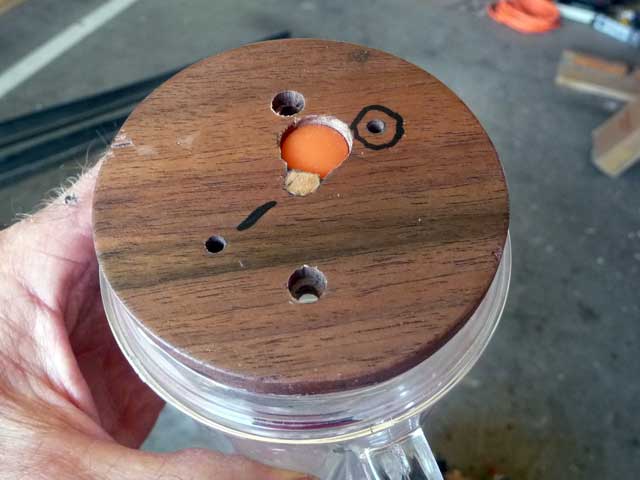
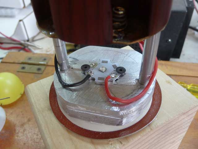
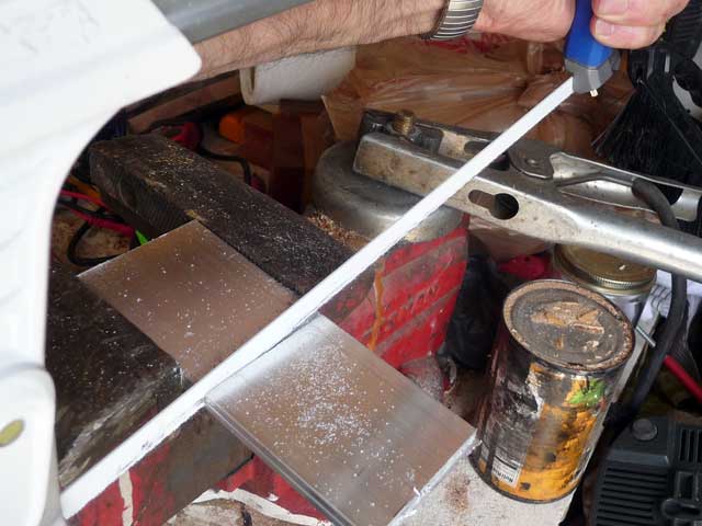
Yet another change is to the upper end where the LED mounts. Previously I had a wood spacer ring. In part the spacer was there to drop the LED and remote phosphor lower. If the LED was mounted to the metal cap directly the mug jar top metal ring / band obscured the phosphor dome a little. I have replaced the wood spacer with an aluminum block.
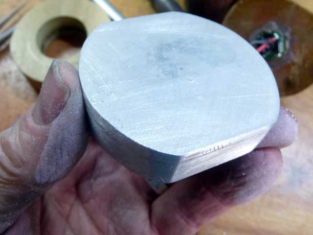
I calculated ½” to be a good thickness. Not wanting to drive over to the metal supermarket I decided to make a block from 2” wide x 1/8” thick aluminum strap material I had on hand. Four layers. Hand cut…
I used 10-32 machine screws to hold the alignment. Arctic Alumina adhesive was used between each layer. It seems to hold very well. Clamped in a vice waiting for the cure to complete.
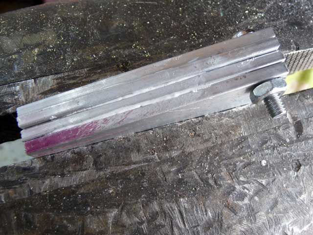
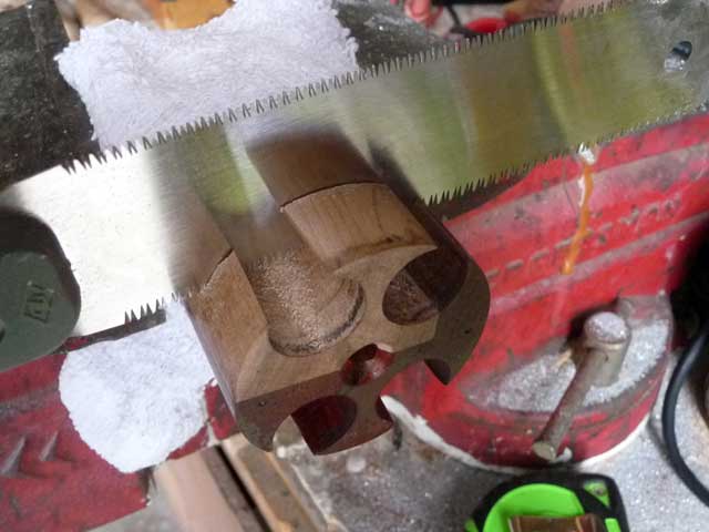
I scribed the curved ends to match the shape of the cell block.

Then did a rough cut with the hacksaw.

That was followed with some use of a coarse bastard file.

Then a finer cut file… followed with some sandpaper. It is far from a perfect finish, but is hand made.
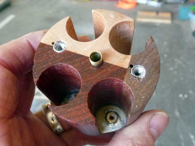
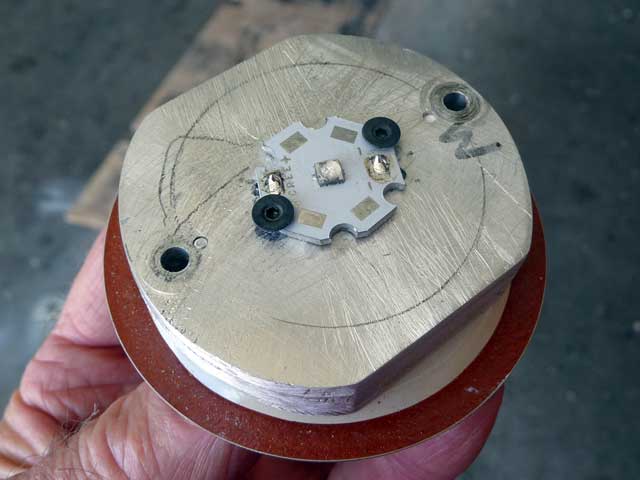
Drilled and tapped some holes. There are a couple of extra holes, one with a broken drill bit embedded in it.

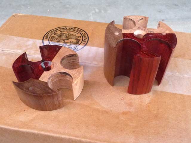
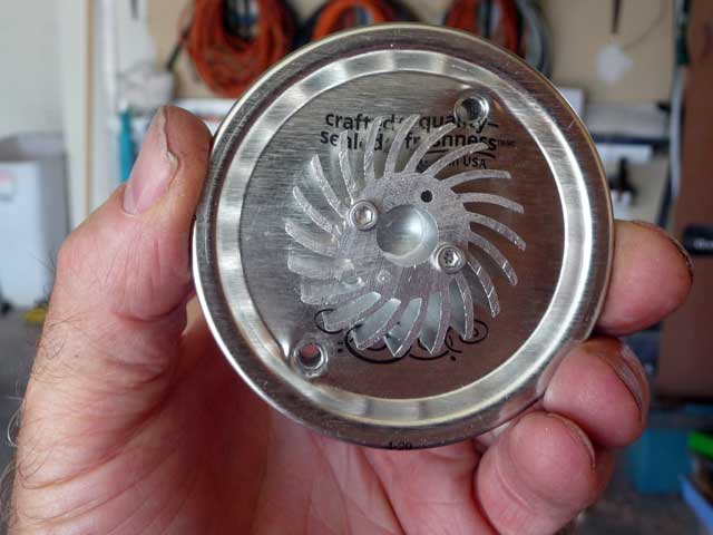
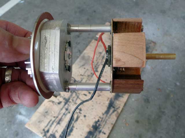
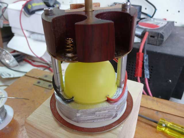
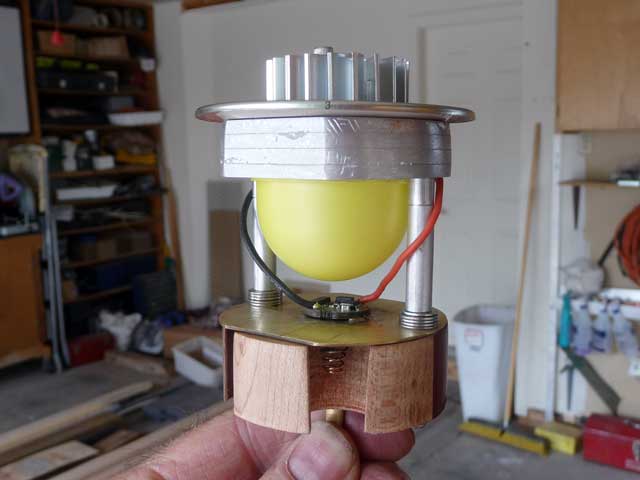
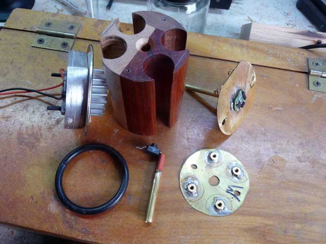
The aluminum block will mount to the underside of the metal mug sealing lid. The LED mounts to the lower face. The finned heatsink mounts to the upper surface of the sealing lid. I used Ceramique 2 heat transfer paste between the mating surfaces. Here are the major components, except for the mug itself. The assembled aluminum block, LED, sealing lid and heatsink can be seen leaning against the cell block. The switch brass post shows the heat shrink tubing.
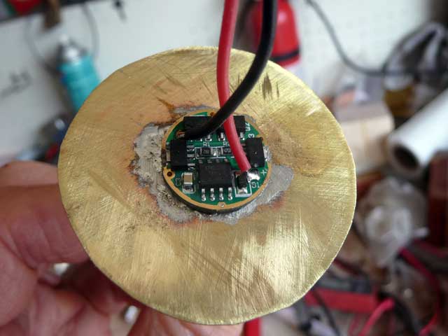
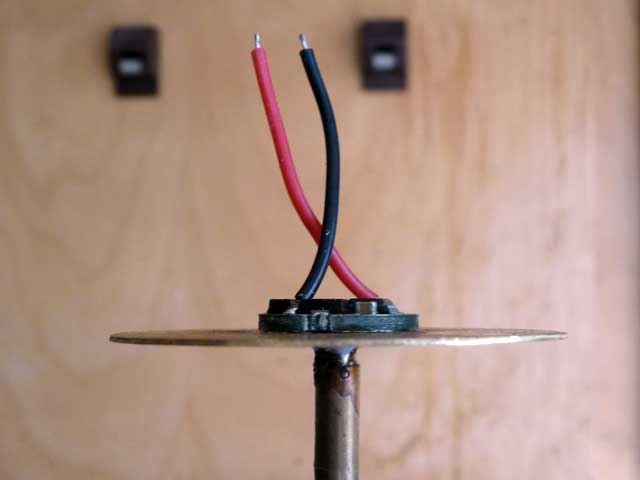
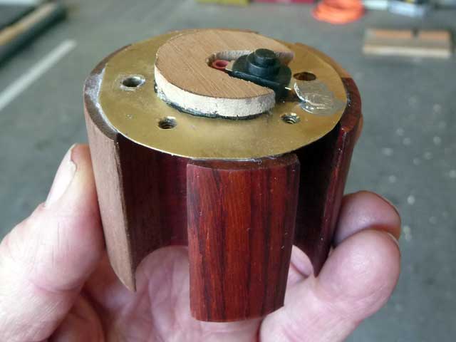
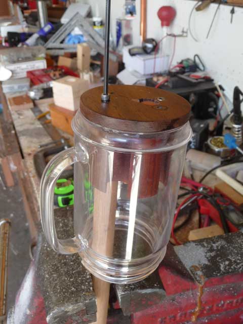
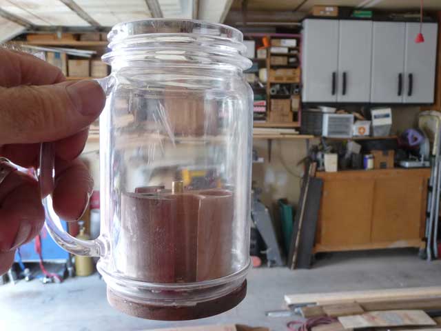
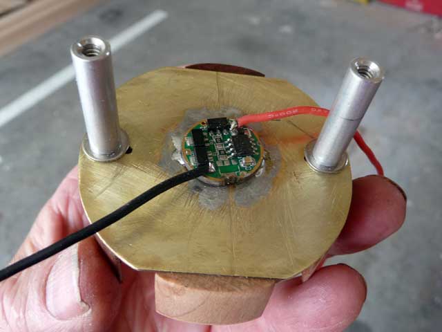
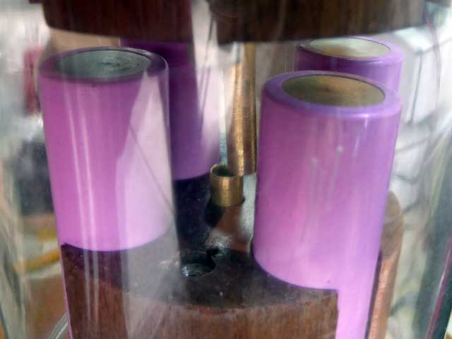
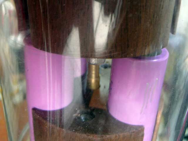
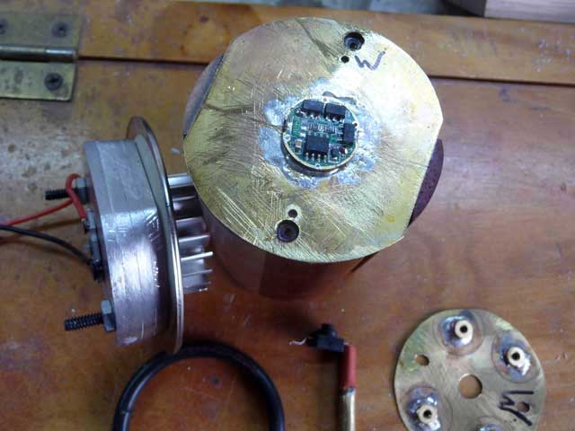
I’ll finish this set with a shot showing the new driver plate in position on the cell block upper end. The Nanjg driver is soldered over the center hole in the plate. The center contact (+) tube extends down through the cell block center to mate with the tube from the switch. One slides inside the other. My meter can’t read any discernable resistance difference between a single continuous length of brass tube and the section of one inside the other.
More to come…