Less resistance = more power flowing = brighter LED
Too much power flowing can mess up your driver function though, so be mindful of that
Less resistance = more power flowing = brighter LED
Too much power flowing can mess up your driver function though, so be mindful of that
Ok, that makes way more sense. You might want to add that picture to the OP, a picture is worth a thousand words as they say.
IIRC the stock switches in the S2 are the small 1288 correct? I have a bunch of those laying around so hopefully they will work.
Many thanks!
I yeah I should add it or another one. I’m due to go and make sure all the links are still active too.
If you get Rev5a, don’t forget to order some of the little slide switches too.
Yes, the S2 uses the 1288.
Ok, think I am about ready to order some of these. Think I am going to go with pyro1son switch as I can’t find the right slide switched on digikey for cheap (making an order anyways) plus if I want to turn it off I will just lockout the tailcap I think.
Or do you know of the right switch from digikey? Might grab a set of the 5.1a as well.
My only real question now is what components should I grab while making a digikey order anyways? I already have some 470, 560, 680ohm resistors in the cart for the bleeder. Any other sizes I should add for the LED’s themselves?
I have no idea on digikey, but here are some on ebay shipped from the US. They’ll probably get to you long before the oshpark boards.
It’s up to your preference anyways. I can understand having access to the pot from the bottom, but I prefer having “presets” of levels I can just jump between with the switch.
We started using pots because it can be annoying to be swapping resistors trying to find the right balance. For pots get either 50k or 100k. For LED resistors it could be anywhere from 2k-50k based on how bright you want them to be and how your leds behave under low power.
Ok, got the boards ordered, I look forward to playing with them.
Very simple and good idea PD now that I see how it is all working together.
Unfortunately it’s still a slightly custom process thanks to the differences in machining between lights. To give examples, I needed to use the thin 0.8mm boards on top and bottom for an S2+ with metal switch cap, but needed to use a thin bottom board and thick (1.6mm) top board for my Astrolux S41 with rubber switch cap. Otherwise the switch itself was too far back (pressed against the rubber) and it didn’t have enough travel to reset.
Yeah, I am used to modding, not scared of some custom work.
After years of this type of thing I have learned to buy the most universal parts ahead of time since you never know what you might want to use them in.
Hi pilotdog68, could you give me an advice, which one of this boards (with 2 leds) is easiest to build with parts available from OSH and ebay, for use on nanjg 105 and A17-DD and BLF X6 drivers
Thanks :+1:
are you saying you want a version that only uses 2 leds? most of the better versions you’ll need at least 3 to have a balanced look.
So it looks like it’s time to update the OP with new pictures and fix broken links.
If someone is building one soon, or already has pictures, or is willing to take apart a light:
I need some pictures of how the newer versions are constructed.
I’m looking for high-quality macro shots of the top of the board, how it’s stacked, etc. Basically an updated version of what are now the bottom four pictures in the OP. I would take some myself, but I only have a cellphone camera to work with. I’ll do that if I must, but I know we have some better cameras (and lighting) among us.
Also, if you have other suggestions on how to better organize this huge amount of info, please let me know.
Here in my Eagle Eye triple build you can find my photos of the tailcap build too. Not all the best shot because I used phone too but I hope you can use some of them:
EE X6 triple build and lighted tailcap build.
This is super nice, I didn’t see this version before ![]()
any instructions how to make that switch, which board to order!
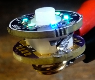
Hi I made this to my Eagle Eye X6. It has BLF A17DD driver. I used 470 Ohm bleeder resistor on driver side and 47 KOhm resistors on the ring led PCB’s bottom side for each pair of leds. And some blue 0805 leds from ebay. The PCB is this 5.1 version
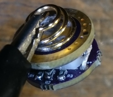
Here you can see the place for the 3 resistors at the bottom:
The led board’s negative contact is wired to the switch leg which goes to directly to the battery spring:
The positive goes to the other leg of the switch.
The spring bypass is not necessary if you don’t make a high current setup as a triple led light and you can use your original switch board with spring and switch. Just leave the washer out from the top of the switch because the led ring board function as the washer too. And also replace the swicch boot with a translucent one. This board is good for 14mm diameter switch boots.
Thanks for the info ZozzV6, I just ordered 6 x 17mm High-Amp Switch PCB copy and 6 x PD68 Illuminated Switch - 16mm Rev5.1 copy, alredy have some tiny leds and SMD resistors as well as A17-DD drivers.
Now I wait ![]()
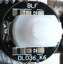
For pictures these may be ok as well? This is the last one I built, for an S2+:
I tend now to make the connection bewtween ring and switch-board short and stiff (filling the entire wires with solder), I fix the ring well in place like this so nothing will mangle when the assembly is screwed in place.
I have had issues with this as well. I solved it by super gluing the ring to the top flat parts of the switch (after I was done soldering it)
I’m considering making those vias big enough for 0.025” header pins now that I’m using them on the TripleStack
I got these tailswitches, after paying extra and some delay and confusion (and a wonderful firm explanation by OL in the seller forum about what belongs in a host)
I’d like to make this into an amber, rather than blue, emitter — if I can solder this small stuff.
Can’t promise anyone else that they’ll be able to get switches with the hosts described in this thread
Sweet, the board functioned as washer as well :+1:


