Just sent 2012beautifullife this question with regards to this:
From what I see in the photos, these boards seem not to have dielectric layer over the central (thermal) pads; I mean, the boards seem to be of “direct thermal path” type. This can be easily tested by checking the presence of electrical conductivity between the underside of the board and the mentioned central thermal pads with a multimeter.
May you comfirm this?
Thank you. :-)
Wait huh?
XP footprint is 3535 yes? This is 7070.
Do the emitters work 2P2S?
Does this means one inputs 6V yet the each XHP70 gets 3V?
Oh man I would not dare trying to get 4 XHP70s on there…now that is, but after getting to know the nodding better it seems very cool to have this in the Jaxman Z1 fully focussed
Only need 4 Z1s like that to play chess on a wall
Hey I am just repeating what they say
I thought the XHP50 was compatible with XML/XML2 footprint, that the XPL (hi) is different AND that the XHP70 needs larger pad
You write about XPL footprint and description says 7070 so sorry I am really lost here
LightRider, the vendor told me they are not. However, in my experience, lots of eBay vendors know actual Jacksheesh about their products.
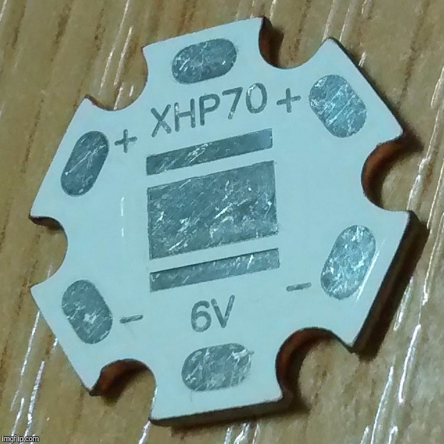
Look at this photograph I took of an XHP70 baseplate I received from FastTech which actually is DTP:
This board probably came from the same factories the ones this vendor has. Take a look at it, you'll see the thermal pad is somewhat “depressed”, you may be able to spot a circumventing line around it: that's because the dielectric layer is missing there.
I see the same on those quad 3535 boards… if those are actual photos of them, I'd bet they are DTP. Of course I may be wrong on this… but you can see my point.
^ Astute observation. The board in the OP does appear that it may be DTP. The 3 volt 4 up XP looks interesting. Anyone know any optics that might fit it?
ImA4Wheelr, as far as I can see on the different board pics, I see a proper top copper layer layout for the 6 & 12V versions; that is not the case for the 3V one, which looks the same as a 6V. In a 3V baseplate the central strip interconnecting all of the leds' inner leads should be one (maybe the negative) pole, whereas the other pole (maybe the positive) should have tracks embracing both sides.
Definitively fishy yet, as I said, lots of eBay vendors know @#$% about the real product, maybe the real vendor hires a handful of employees with multiple eBay accounts (in order to flood/monopolize the search engine) and gives them generic pre-designed item ads; they do nothing more than telling daddy “send this or that to Joe/Jane Blowsgoats” and answer clients' questions the best they are able…
Bruno28, led baseplates usually are Metal Core Printed Circuit Boards, which means they need a dielectric layer to isolate the core from the track layout, and this dielectric's thermal conductivity (thermal goo class ±) is a bottleneck with regards to maximizing heat transfer from the led die. In Direct Thermal Path boards the dielectric is nonexistant where the led's thermal pad goes, so solder goes in there for at least a twentyfold heat transfer ability improvement on that layer surface.
Cheers ^:)
Original post date: Mon, 09/05/2016 - 12:45. Information added; grammar fix.
Been browsing the store and Yes I am wondering. They carry some crazy SHtuff and stupid low prices. They need reflectors to match the odd stuff.
Even if the pics are Genuine Cree, what are you going to get?
Want XP-G2 neutral on 12mm but I am hesitating on the click.
I see what you mean. Weird how the 3V and 6V have the same scratches (underneath the solder resist). I ordered some of each last night. I’ll report back when they arrive.
CRX already has that image in his LEDs & other stuff thread. It’s stickied and chock full of similar good info. Not a bad place to spend time learning.