^
That sounds like good news.
I’ve been pulling my hair out trying to find 0.025” header pins. The ones you purchased are $20.00 shipping to Canada, a bit much for me.
I’m a huge electronics noob, I believe that the issue that I’m having may be the search term “0.025”. I’ve found header pins listed as “0.64mm” or “25mil”, I get way more search results using those terms.
Could someone please confirm that these are equivalent: http://www.ebay.com/itm/10x-40-Pin-Male-Header-0-1-2-54mm-Tin-Square-Breadboard-Headers-Strip-USA-/150838016410
The specs list .64mm sq. with a 3mm and 6mm pin for an overall length of 11mm.
Yeah, those should be perfect. 0.025” is “25mil” and = 0.635mm
They are actually just a one-piece pin, but 3mm and 6mm stick out on either side of the plastic holder/spacer
Ah, Thanks! I knew that 0.025” = 0.635mm, but did not realize that “mil” referred to one-thousandth of an inch.
Do you pull the pins out of the plastic bit before using them, or leave the plastic bit on there? I’m using the pins for some lighted tailcap v5.3 boards that I ordered today. I just posted my question in this thread because it was the only place that I found a comment about sourcing the pins.
I take the plastic off, but I don’t think it matters. You may be forced to remove it for clearance
Just got my boards today. Hopefully I can build one tonight or tomorrow. I’ve been waiting for these to finish a d80 build for my brother. I have the lighted Tailcap assembled and everything is ready to go but the driver. Hopefully the circuit works well with the bleeder.
I think he’ll like it. He told me to have it done before hunting season. I’ve been noticing him steal my parents four wheeler so I think that is my que. time to get it done ![]()
Yeah I haven’t thought about where to put a bleeder on this layout… I’ll have to think about it when I get my 20mm contact boards. I suppose you could still stack it on C1… I don’t see why not
I think I’m going to put it on the spring side of the board. I’ve been doing that with the new fet +1 boards from Richard and it has worked well. Then I can swap it out without removing the driver. On those boards there is a trace and via carrying the plus signal that I scrape clean and put the resistor over that via connected to the ground ring. I see I might be able to do the same on these boards. One of the extensions of the plus/spring pad goes really close to a via with the ground signal. I scrape the solder mask off of that via and put the resistor there.
btw hopefully the three-pointed spring pad works for everyone. It’s perfect for me because I reflow my springs with solder paste to keep it clean. I tested it on one I already received and it worked perfectly that way; a good strong bond.
You’ll want solder that flows easily if you are using an iron though.
Well. I built a triple stack driver today. Aligning the pins proved to be more difficult than expected. And it didn’t help that I accidentally ordered 2oz contact plates as well. Two of the via traces broke loose when trying to align them. The vias were lined with solder mask and were difficult to solder too and I had quite a bit of troubles actually.
But it is built now and it’s perfect for what I needed. I’m going to put it in a blf d80 where there is room in the driver cavity, and a retaining ring that would normally not work with triple channel layout. The spring pads worked well for me. They required less heat to get the solder to flow and it seems to hold just fine.
Now that I put one together, I think I learned some tricks. Hopefully the next goes better ![]()
I have yet to flash the firmware. Hopefully I’ll get to that tomorrow.
Yeah, If I had made the vias tighter that would help with the alignment troubles. I realized when I got them that they are really quite big.
I plan to do it this way:
- solder the pins to the contact board (only from the top) with silver solder first, while the top is already loosley stacked to keep the pins straight.
- populate the contact board and top board with components.
- solder wire to LED- ( or do this at the end, depending how much clearance I have)
- trim the pins to length and solder the pins to the top board
Ok. I have the triple stack built and running bistro tripledown. It’s working with a 680 Ω bleeder and a 12k resistor in front of 6 green 0604 LEDs in the Tailcap. It was some work, but I’m excited now! The thing that work for me in the end was to use 22awg solid core hookup wire for connecting the vias. I solder the bottom via first then I clipped the wire at about 2cm then moved on to the next one and cut that one at 2.5cm. I let the wire length grow like that till all 5 were soldered. Then I feed the longest wire into the top board and then the others one at a time while sliding down the pcb. The wire was malleable enough to allow a perfect allignment. I would want to mess with the triple stack when not needed, but with lights that have retaining rings it’s the best option for sure.
Did my first of the TripleStack’s in the OP. The driver is definitely more work assembling that a traditional design, but for me it’s worth it for the clean look on the battery side. I also could have compressed it quite a bit vertically, but there wasn’t any reason to with the L2’s big driver pocket. I’m very pleased with the clearance for the programming clip.


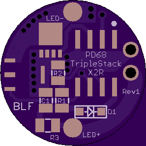
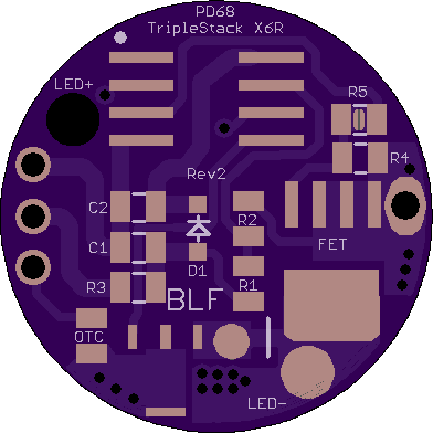
Copying here my TripleStacks made specifically for the EagleEye X2R and X6R.
For the X2R, you just remove the top board on the original driver, get rid of the extra header pin, and solder this in its place. For best performance, you will also want to solder the big pad on the bottom to the top of the USB connector on the charger board. Headroom is tight, but the LED wire pads should line up perfectly with the holes in the shelf. If you order from Oshpark, be sure to get the thinner 0.8mm size. Also note the FET is the smaller LFPAK33 size.
……………………………………………………………………………….
For the X6R you will also use the stock pins. You will run ground wire from the charger board to the pad/via by the FET. The LED+ hole is over a spot you can safely drill through the charger PCB to bypass the spring/PCB. I’ll illustrate all of this with pictures once I finish my X6R mod. Also be sure to order this one in the 0.8mm size.

Looks good PD!
Thanks! The X6R is probably the best board I have ever made. I think even DEL would say the circuit is routed as well as can be, there should be plenty of clip clearance, Tom would be happy with the power path, and it even passes my aesthetics standard.
Well done pd. Love your work. :+1:
Hey pilotdog,
I’ve been lurking this forum lately and I’ve been reading a lot of your posts. Anyways, I really want to build a 17mm rev2 but I haven’t figured out what parts I need. Do you have a list somewhere of the parts needed to populate the board? I’ve looked but I couldn’t find it.
R1 19.1k (or 191k)
R2 4.7k (or 47k)
D1 Reverse polarity schottky diode (sod-323 I think?)
LFPAK56 FET
Attiny25 (SSU?)
C1 10uf X5S or better
OTC 1uf X7R
Caps and resistors are 0805
Another user reported an issue with the Triplestack X2R board. It seems I may have specified gaps closer than Oshpark can make reliably. There didn’t seem to be too much demand for that one, so for now I have taken down the link. If you are interested in ordering it, just let me know and I’ll fix the issue and repost.