I have seen this type of light before. Nothing is new under the sun, but I keep visualizing the finished light and decided I might see if I can make it look like what I already have pictured in my mind.
I don't even have four lights the same color yet...
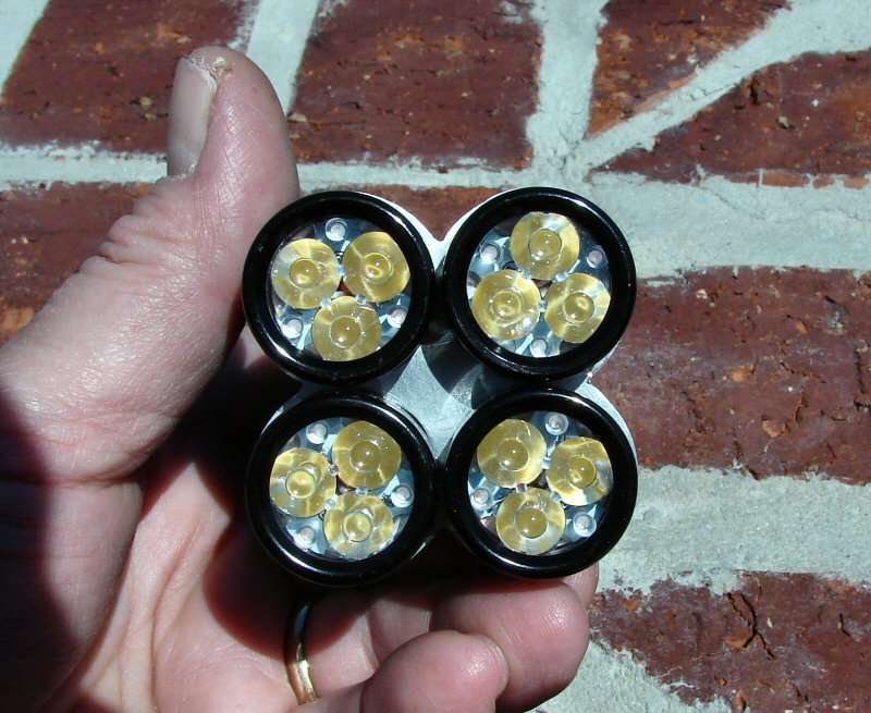
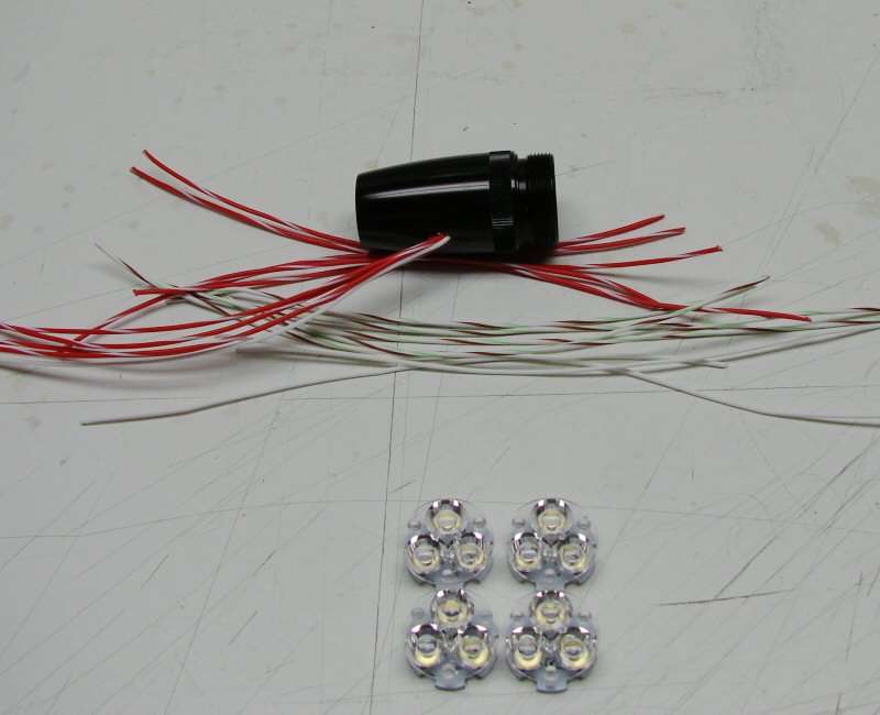
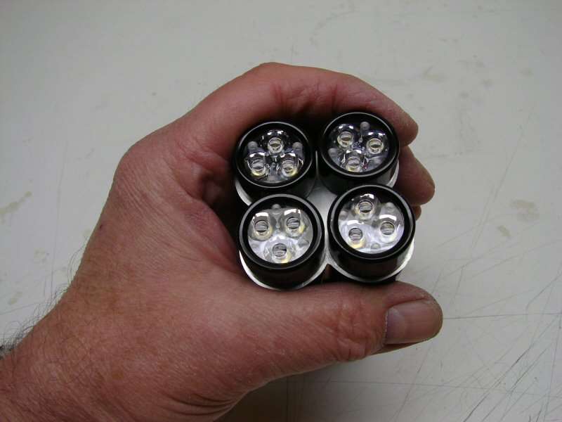
12 Nichia 219s, 4 of the NANJG 3 amp drivers (master/slave), 4 TIR optics, 4 (maybe cut down) Mini-Mags, some copper and a cut down Judco switch.
I have no clue as to how this is all going to come out, or if it will even make it past the circular file, but I just have this idea in my head and can't get rid of it till I try.
Thanks to Rich and to all the manufacturers of those crazy looking four headed lights, for keeping this idea alive till now.
---------------------------------------------------------------------------------------------------
03-30-13
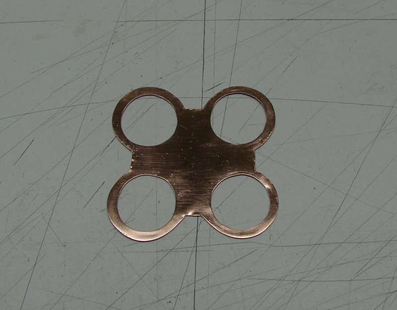
I have done a little today. Not much actual work though. Here's the only thing I managed to get done.
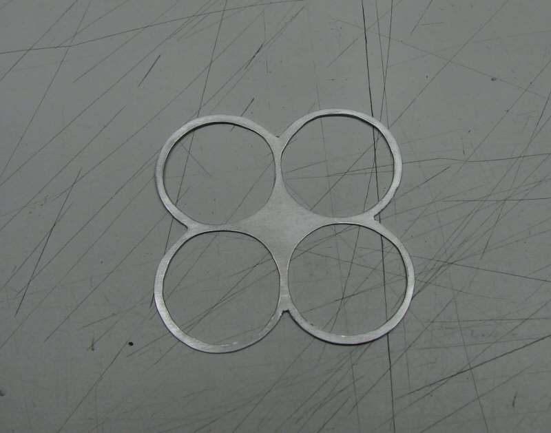
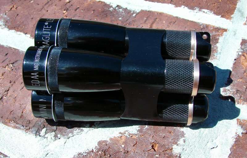
It's to hold the four heads together. It's not very pretty at all. Pretty shabby at best, but, it's hand work. It's Aluminum sheet and too thin, but it's what I had.
It fits and that's the most important thing.
I decided on LED Mini-Mag hosts. I am going to need the extra head length for heat sink and all the wiring. Oh, I hate that part...
I managed to get the tail end plate made today as well. It's copper and the center copper pipe will be soldered to it later. Made the same way as the front one. Just a piece of plate, mark the holes, drill and Dremel them out. Some filing on the outer edges, to make them somewhat close and it's done.

----------------------------------------------------------------------------------------------------
03-31-13
Time for a break. I've been working out in the shop for several hours. I have all the heads milled out and the copper couplings milled out. I have the components laid out and I have drilled for wiring.
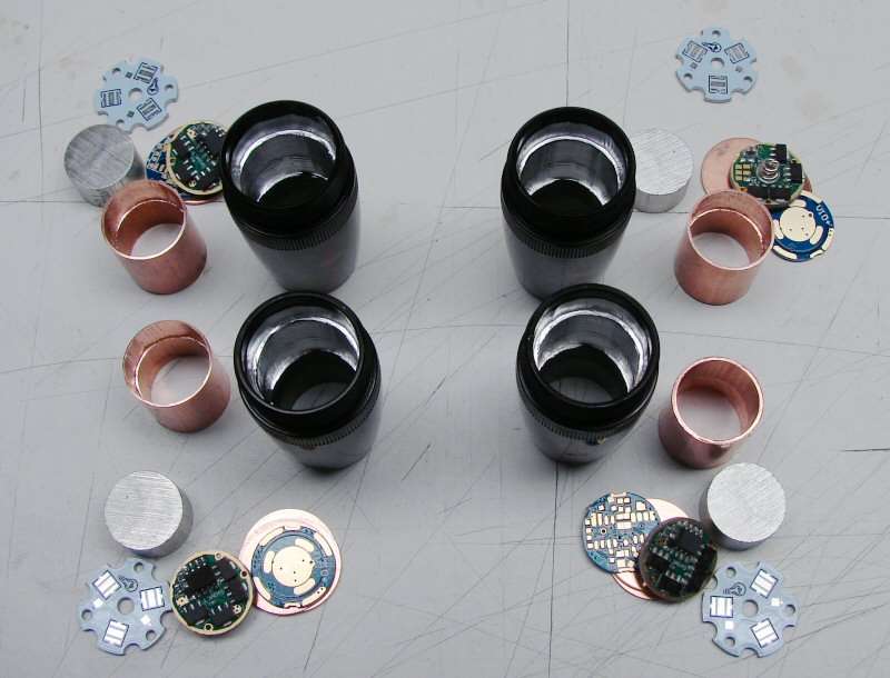
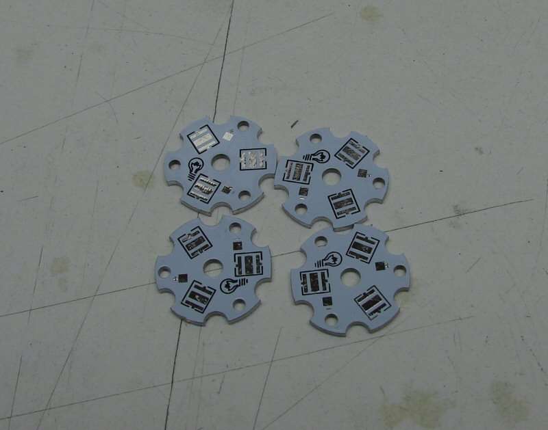
Heads, drivers, heat sinks copper couplings, led stars and contact plates.
Since the positive wires go straight from the batteries to the led stars, I need to get past the driver. I opened up one of the thru holes on each driver, so the positive wires will be able to get past the drivers.
I have drilled all four heads, so the wires can pass out of them and they will all end up in the center 1/2" copper pipe.
The copper couplings have been slotted, for wire clearance.
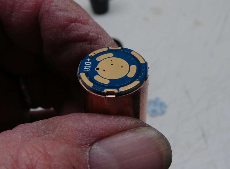
The contact plates will be for the batery positives to touch against.
I still have plenty left to do.
- Reflow 12 leds
- Wire the stars
- Wire the drivers
- Cut down a Judco switch
- Cut down four bodies and thread them for tail caps
- Put the "pills" together
- Wire everything up
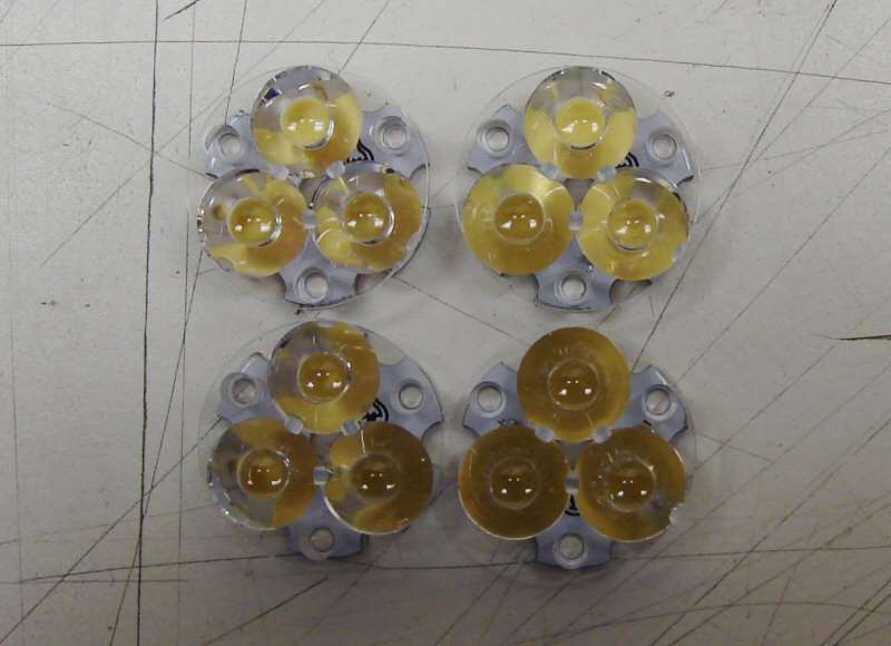
LEDs are on stars
I cut the wire needed to wire up everything. How the Hell am I going to stuff all that wire into one 1/2" copper tube? I didn't really think about it, till I got all the wire laid out. 5 wires in the head for the Master and 4 wires each, for the other heads, plus the switch wires.
-------------------------------------------------------------------------------------------------------------
04/01/2013
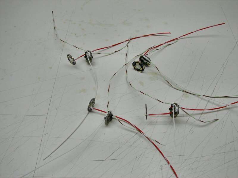
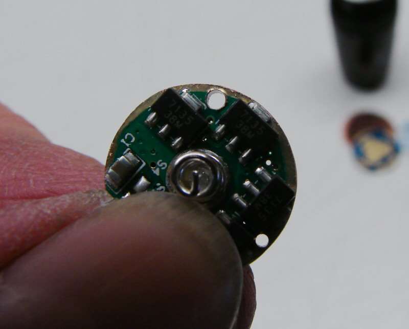
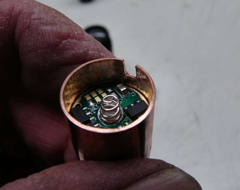
This could should be an April Fools joke, but it's not. The drivers are wired.
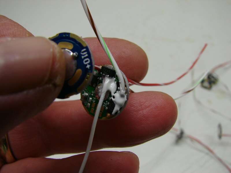
White is solid wire and is for the Master/slave circuit. Striped is Ground.
Red/white is Power from the battery. The wire is soldered into the top board, which is just the contact plate for the battery+.
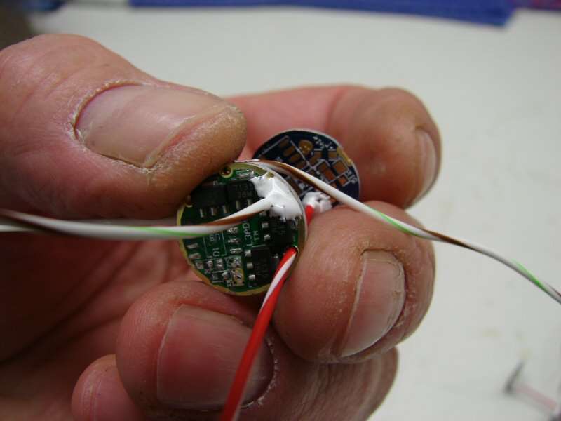
Striped is Negative to the LED and the Positive goes right through the driver, to the LED.
They have not been bent to shape yet, just soldered. They are much longer than needed, but I would rather cut some off than to do it again. All the joints have Artic Alumina Adhesive on them. I find it helps keep the joints from loosening when bending all the wires together.
I have, over time, learned a little about soldering:
- Flux what you want to solder, especially on driver boards.
- Put solder on both pieces being soldered together before making the final joint.
- A little solder is usually much better than a lot.
- Keep the tip clean and tinned.
- Heat the joint and let the solder run up the wire forming a cone. Results in a better joint.
- AA adhesive on and around the joint keeps it from flexing if you are going to flex the wires a lot.
Or just hire someone else to do it...
That's it for tonight.
-----------------------------------------------------------------------------------------------------------
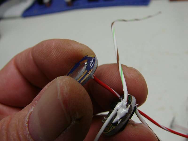
Not much time these days. It's gotten warm here, so gardening is cutting into any flashlight time. All four heads are wired and ready to go. Now I have to cut and tap bodies, before starting final assembly. Also, these heads will have to sit a couple days, since I used Fujik (cheaper than AA), to fill the driver pockets and it seems to take days for that stuff to really harden up.
------------------------------------------------------------------------------------------------------------
04-03-2013
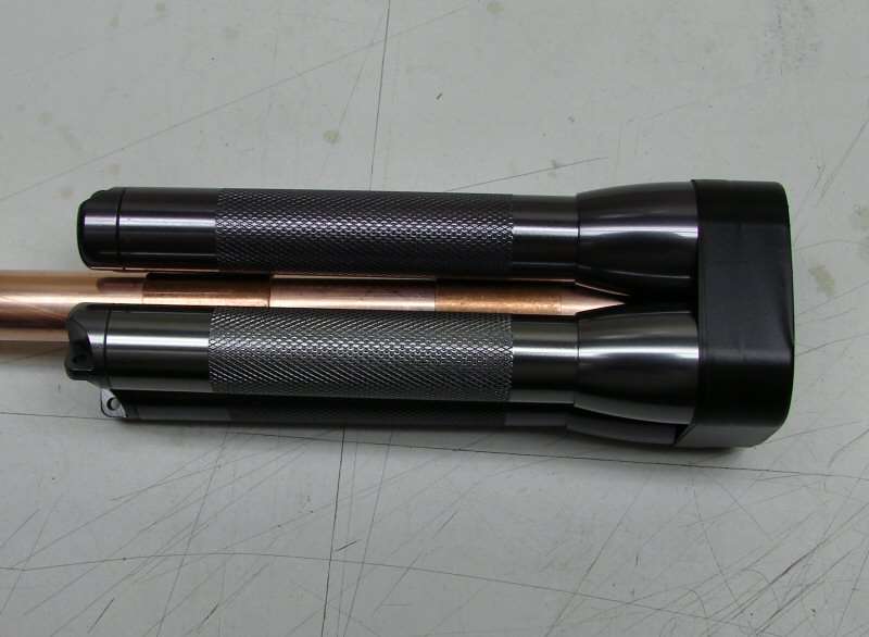
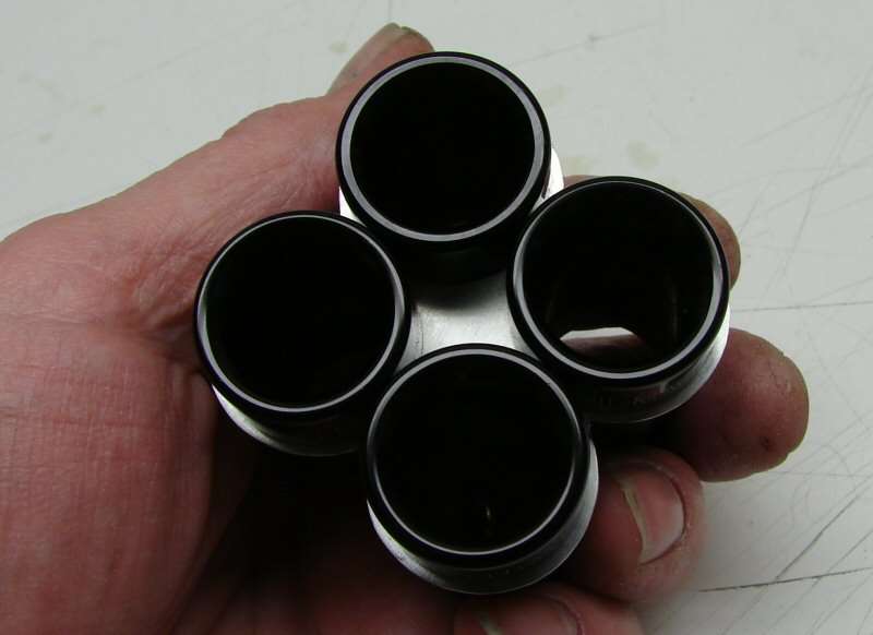
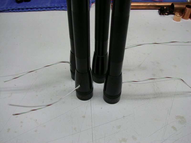
I managed to get the bodies cut down and the switch cut down. It's been difficult, to say the least. I don't think I like cutting down the bodies. They need to be done in a lathe and threaded in a lathe.
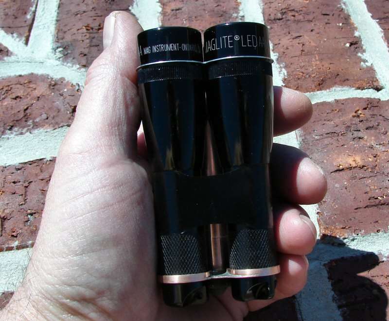
They will take one 14500 each and I milled out the lip inside the top of the body, so the batteries come straight up against the contact plates in the heads. That gives me an extra 10mm to shorten. It ends up that the heads actually look longer than the bodies when done.
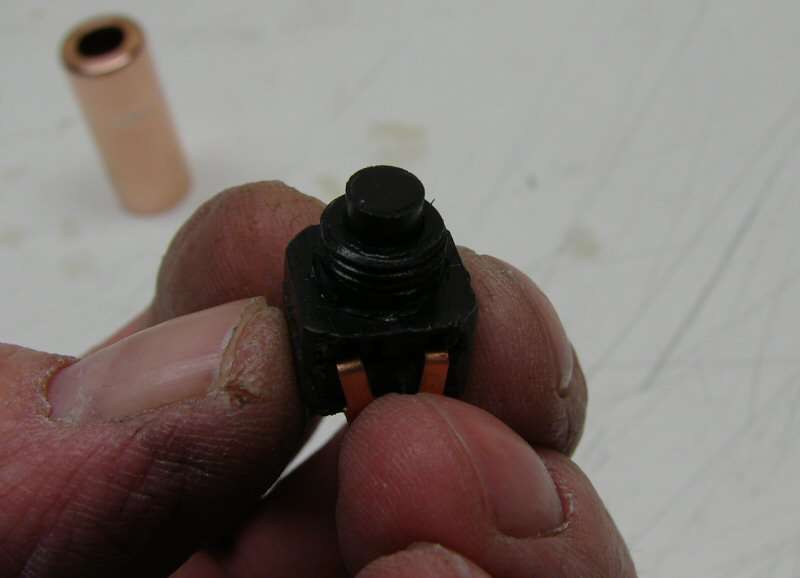
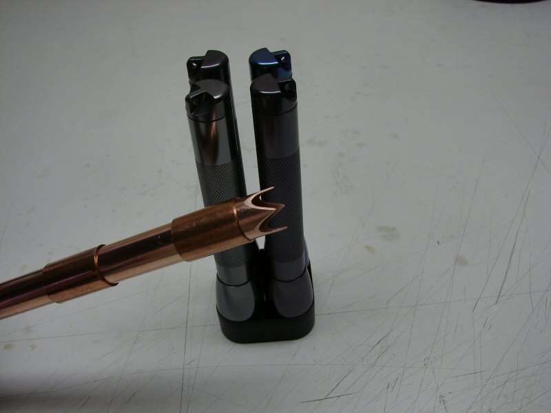
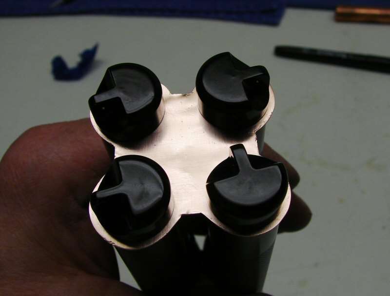
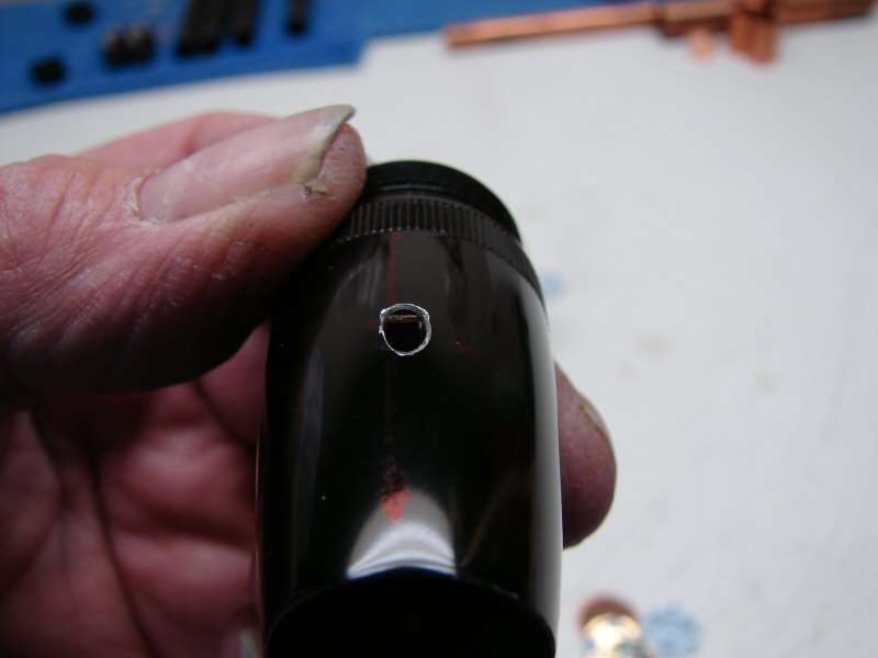
Cut down 10 amp Judco switch fits in a 1/2" copper coupling or end cap.
Sort of looks like a bullet, with the switch in place and the rubber cover. This is a 1/2" Copper coupling soldered to a copper end cap. I will cut it shorter later, when I go to fit everything.
Maybe I will get this all done this week-end.
-------------------------------------------------------------------------------------------------------------
04-04-2013
Let's finish this up!
The wires are together and soldered up.
The switch is soldered up and all the wiring is done. The bottom half of the center copper stem had to be put on the wire, before soldering. Can't put it on after. Now for a little heat shrink and it's good to go.
The top of the center stem has been soldered to the back plate.
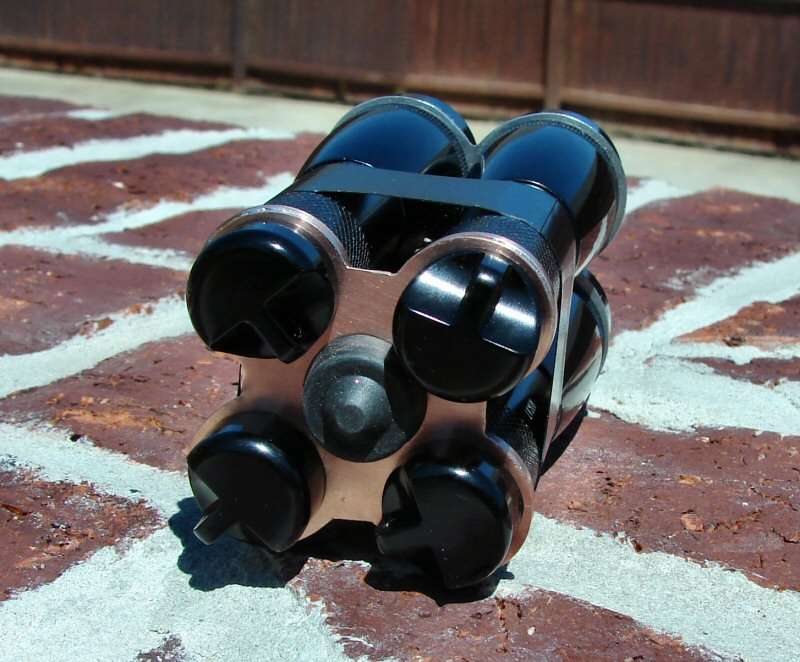
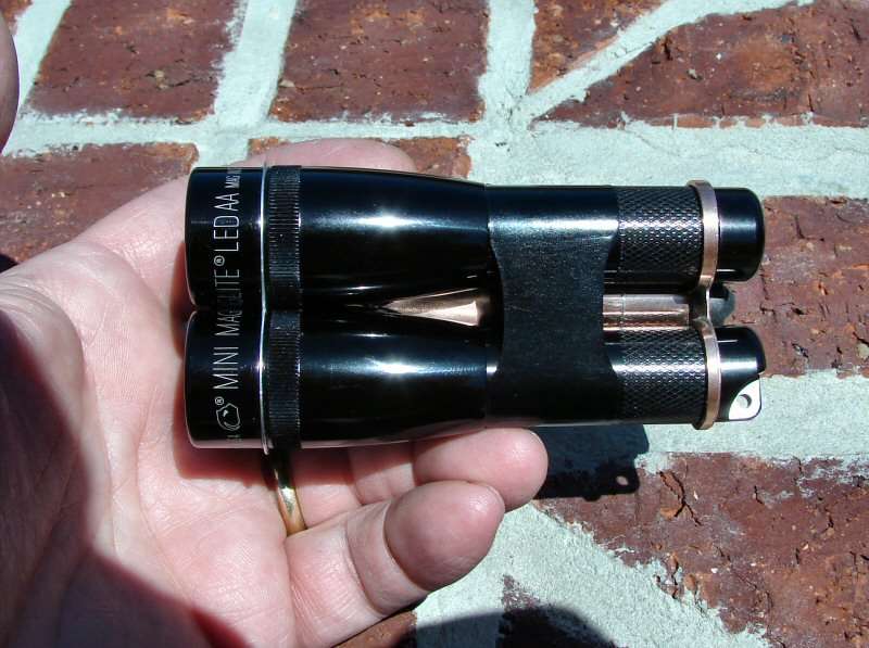
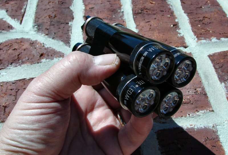
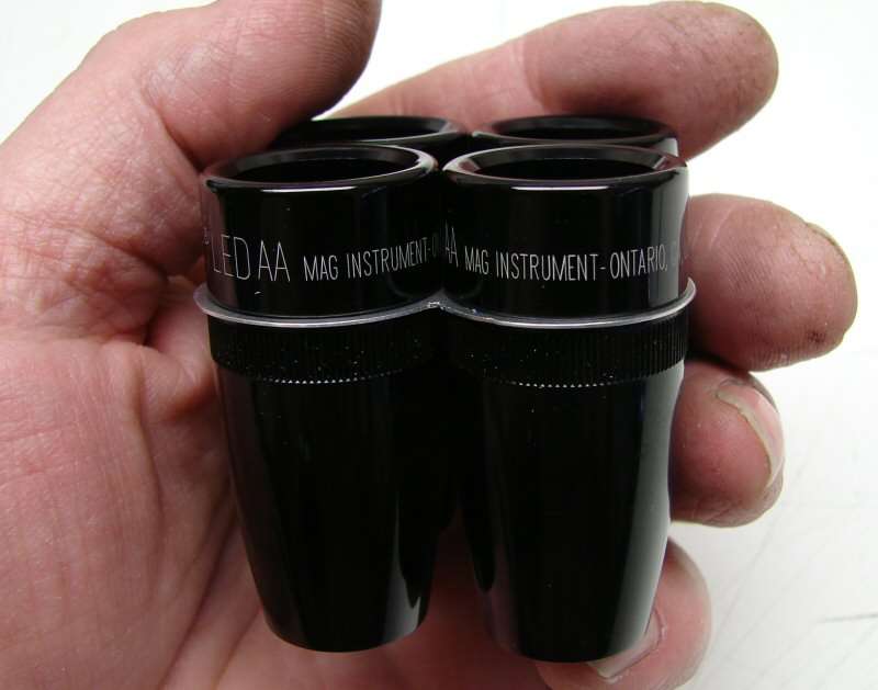
It's done.
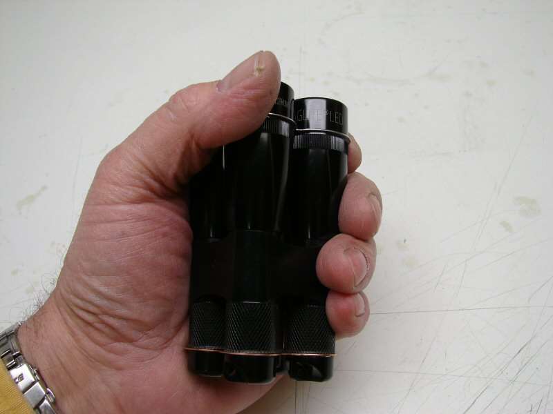
It measures 2-1/2" in diameter, 4" in length and it weight 10.9 ounces without batteries.
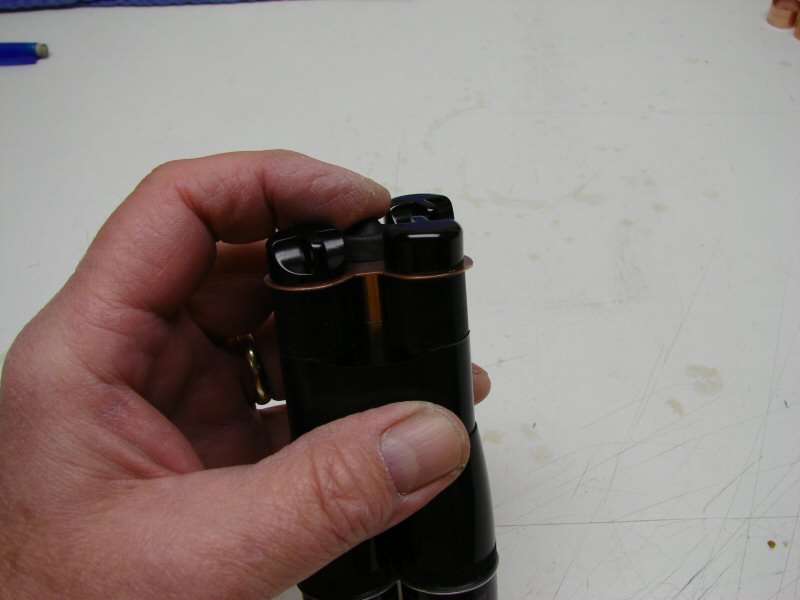
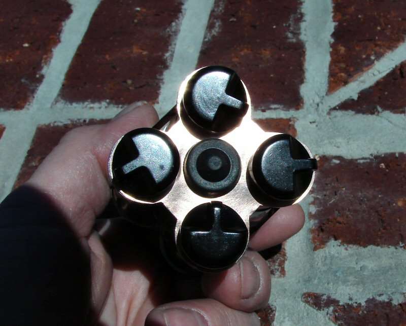
The switch has a rubber boot on top.
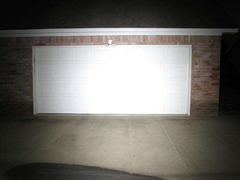
I can't do beam shots yet. I do not have any IMR 14500 cells. I did test the light with 6 eneloops in 3s/2p and everything works, but that's just to test the circuits. It's not enough power to do beam shots.
I don't know when, if ever, I will get to do beam shots.
What would be a safe rating? 1 amp per LED, so about 250 lumens per LED? With the TIR optics, maybe 200 lumens per LED? So at least it should put out about 2,000 lumens as a conservative figure? EDIT: I would chang this figure. 250 lumens@1000mA per led, so 250x12=3000 lumens and take a generous 20% off the top to be conservative, leaves us with 2400 Lumens.
I really want to see it with IMR 14500s in it!
04-05-2013
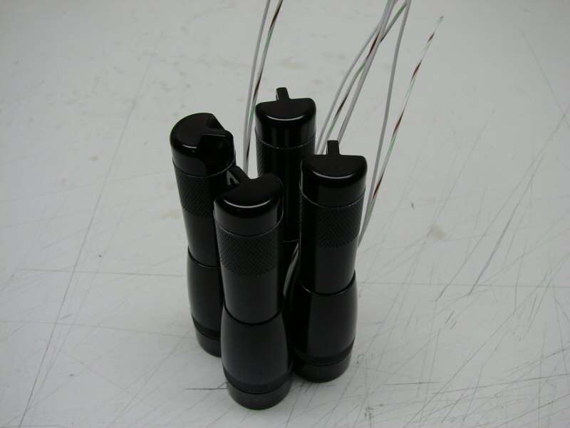
I made changes to the back plate so the bodies are held in place now.
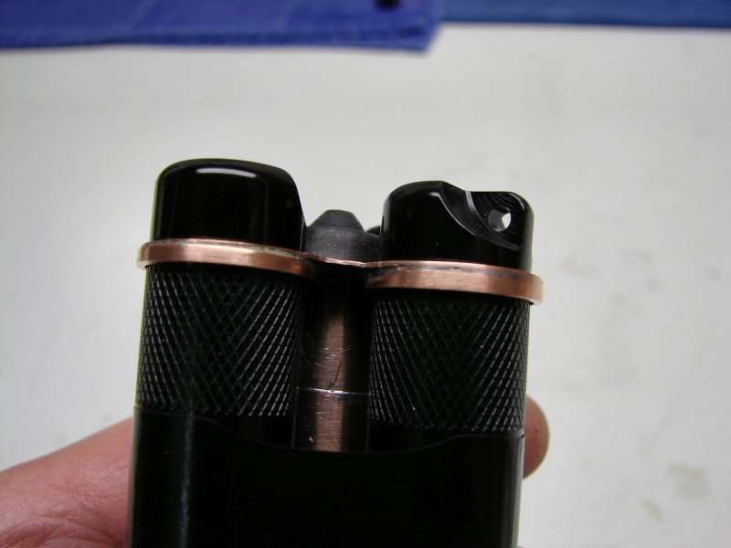
I added copper rings to the plate that hold the ends of the bodies in place. It's a much sturdier setup this way.
I am ordering some 14500 cells to test this light.