10 x 7135 Driver 4 XM-L

Hi,

I have tested much drivers, but none is like i want it (3-mode without strobe and really 3000-3500mA, indifferent which 18650 used....not one 3,2A, other 4,3A)

Now i want build my own driver, based on the NANJG 105 and a "addon"...2 extra 7135.

I´m no electronics engineer and wan´t to ask, if this is wired ok:

(Kaidomain: S009742 + S008618)


I tried it , but connected to the first 7135 just @ the + (Nanj) , no increase in current ..

Isn't it easier If you just unsolder the two AMCs on the left side board (heat the board from underneath and grab them with some twizers) and set them on top of any two of the AMCs on the right side board? It saves a lot of space that way. The second board might be to large to put it inside the pill. Take care to wire the LED with quite thick leads, to make sure these 3,5 amps will go through.

But to fine a work for this old dog ....

Id like to do that , add 4 chips for an extra 1.4A , that would be nice ..

I tried adding just one chip and stuffed it up ... [ to a driver ]

I´m curious about it.....i have 5 tries

Also make sure the batteries you drive it can deliver the extra current. The tweaked pcb also may require improved heatsinking.

At moment, my C8 & Brinyte put 3,6 - 4,3 A (KD C8 driver, but 5-modes with strobe and different mA according to battery).

Driver out of the manafont xml dropin and a "special" battery drives my Brinyte XML with 5,7A....my LED was not excited

And 2800 is not enough for me

If i get my shipment and if it works, i will post here ;)

Good news.

I couldn´t wait on my delivery, so i use 2 NANJG 105C boards to test it.

One NANJG 105C board is "destroyed", only with 2 x AMC7135.

It work very well, my measurements:

High = 3,55A

Mid = 1,10A

Low = 0,17A

I love my new driver :)

I don't even bother. I get the 8X 7135, part out a 4X 7135 driver, take the chips off it, and piggyback them onto the chips on the 8X board. No wiring hassle, have done several and they all work fine.

Have done up to 12 chips-four piggybacked on one side of the 8X board.

Rich

I have try to desolder some, but i think, the 7135 will become too hot.

What´s your technic to desolder it?

(But the 7135 can now be bought at ebay, i saw)

some peapole use this metod:

I put a big blob of solder on all 3 pins at once. As SOON as it melts, I grab it off with tweezers. I use high, fast heat as opposed to lower. Low heat does more damage, waiting for the damned solder to melt. (I'm mil-spec certified for soldering and my training discouraged too-low heat)

Rich

What kind of amps are you drawing on this. I am assuming your using an XM_L led?

I’d also like to see some pics of this as I can’t imagine clearly what the connections look like when piggy backed.

I was able to unsodder them no problem but they are a bitch to resodder onto the board. Retested and could not get any more amps out of it

Any idea's? Think I piggybacked them the wrong way? Any pictures?

thanks

OK, I swiped this from CPF but it's what I do:

Current depends on how many more you add. If I do all 4, I'll get the full 4.2A from a triple XPG. I have one XM-L that'll pull 4A thru this setup also. I don't give a damn if it's overdriven...by the time the LED fails I'd be in the ground anyway! <g>

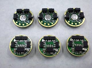
Look at the pic and check your work, keep us posted!

Rich

Great I agree. I put them on the wrong side althought the orintation was right. I'll give this a shot

thanks for the pictures and info.

I like the pic and it helps a bunch but is that the side they have to go on? It looks like it would interfere with the battery and would make more sense to have them on the other side.

I've not checked...but I assume the 7135's are all contected in parallel. So you would be able to add 1-8 additional 7135's to that board with them attached to any/all of the preassembeled ones

So, i got my delivery...

First a 3,5A Driver, second a 3,9A Driver.

I desolder the 7135 with technic by dorpmuller and piggyback it....both Driver work ;)