Suitable for 1 or 2*18650, 26650 or 16340 batteries
Input voltage: 3-4.5V, 5.8V-8.4V
Constant current circuit
Memory function, sets in after turn off
This driver does not use PWM
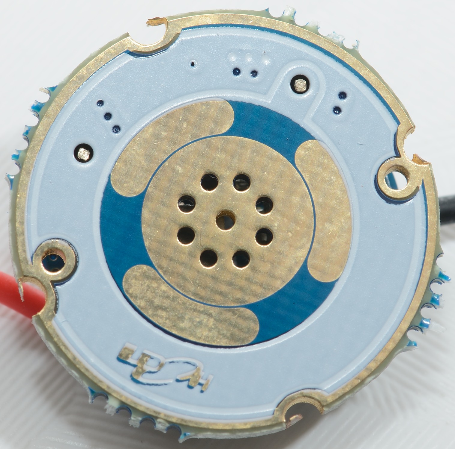
PCB Diameter: 18mm
Contact board diameter: 20.5mm
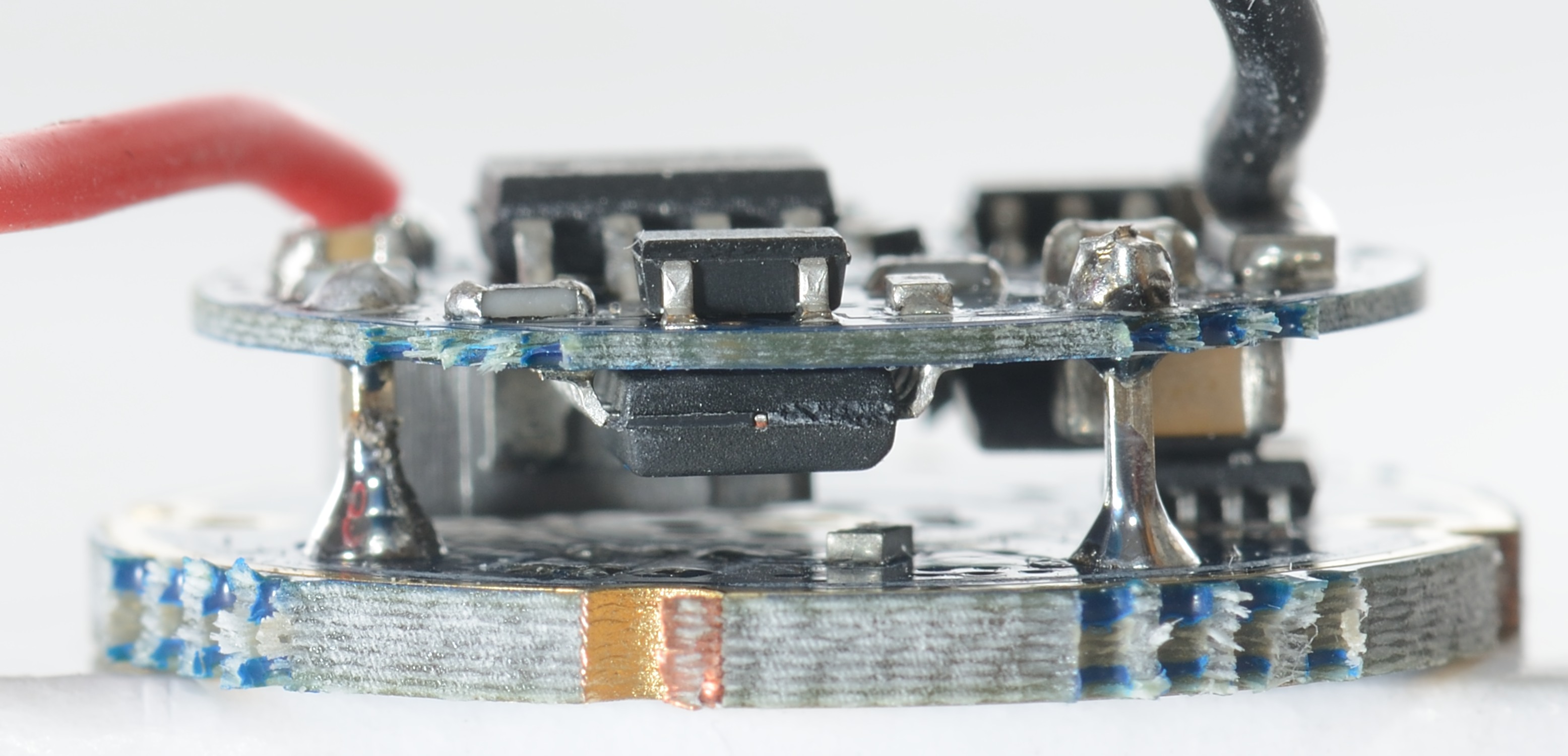
Total height: 7mm
Gold plated contacts
Low voltage protection 1 cell: at 3V the light will step down to low mode and start flashing
Low voltage protection 2 cells: at 5.8V the light will step down to low mode and start flashing
Reverse polarity protection
Copper leads already soldered
Group of modes:
3 Modes: High (3A) - Medium (900mA) - Low (150mA)
2 Modes: High (3A) - Low (150mA)
1 Mode: High (3A)
You can change between the set of modes by waiting 10 seconds on High mode for 1 flash, then turn off and then turn on the flashlight to switch to the next set. You can effectively choose the driver to have 3 modes, 2 modes or 1 mode.
Measurements
Tested with: Cree XM-L2
Diameter: 20.4mm and 18mm
Height: 7mm
In first mode set the driver has: High, medium, low
In second mode set the driver has: High, low
In third mode set the driver has: High only
The mode set selection is done from high mode.
The driver has memory, the actual mode is stored when the light is off for a short time.
A short off/on will select next mode.
Driver is buck only.
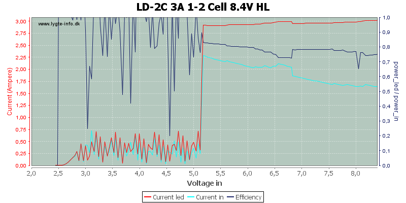
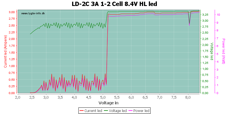
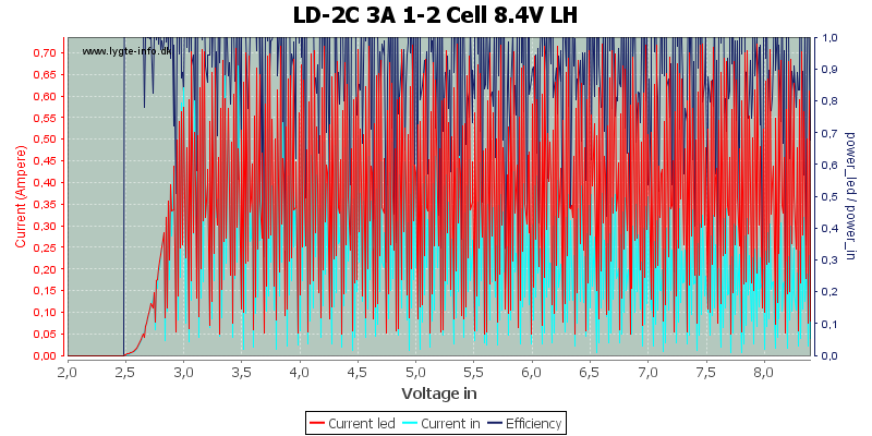
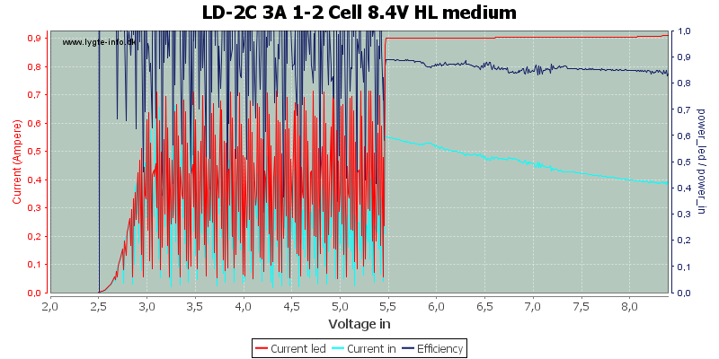
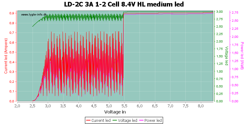
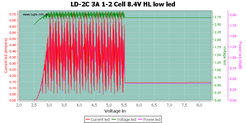
High
The drop at 8 volt is the mode set signal, it is not shown at 3 volt but about 3 seconds after light is turned on.
At about 5.1 volt the driver warns about low voltage, but it does not turn off before the voltage is down to 2.5 volt.
I wonder what happens between 6.5 and 6.8 volt.
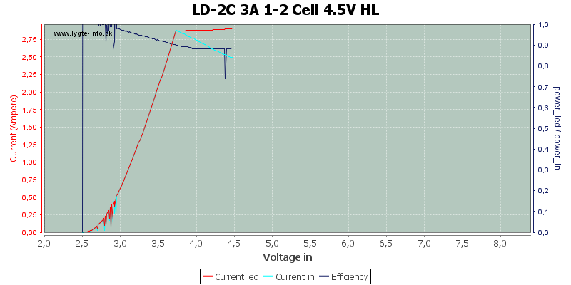
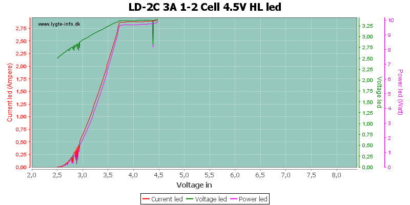
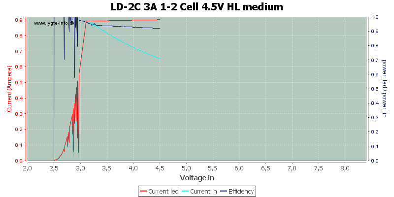
Starting at a lower voltage will select the one battery mode, where the warning first kicks in at 3 volt, but the output starts dropping at 3.6 volt.
Starting from a low voltage and slowly increasing the voltage does not really work. The light turns on at 2.5 volt and goes directly into warning mode, where it will stay.
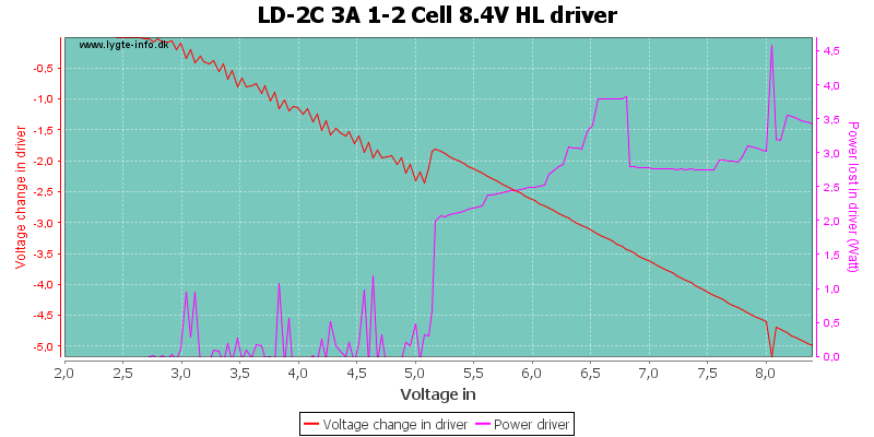
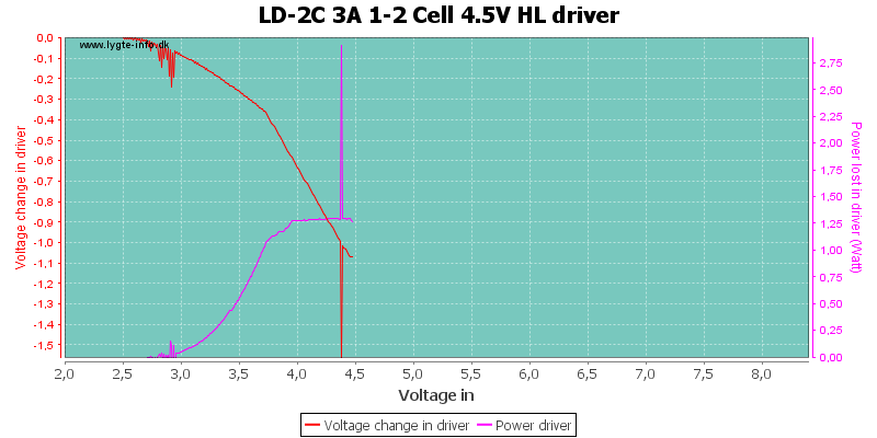
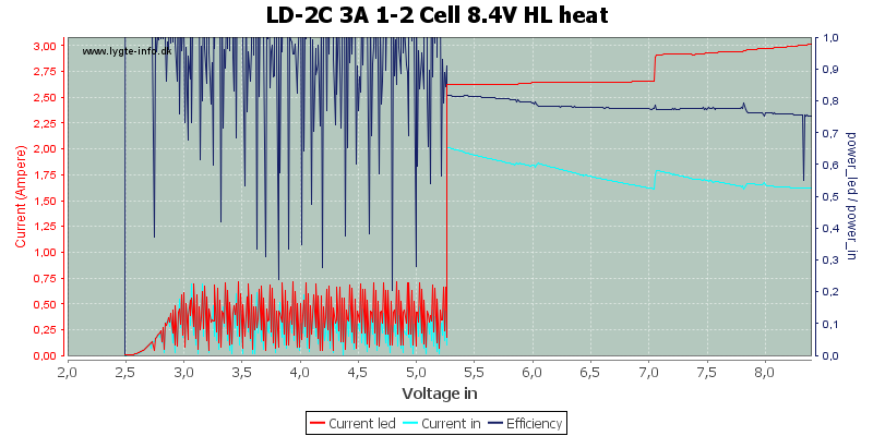
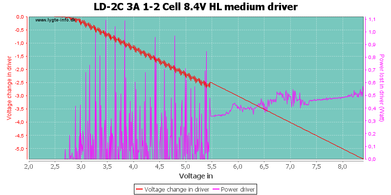
There is a couple of watts lost in the driver and when it heats up, it will reduce power slightly (At 7 volt).
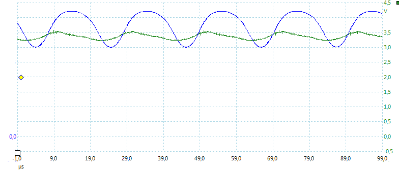
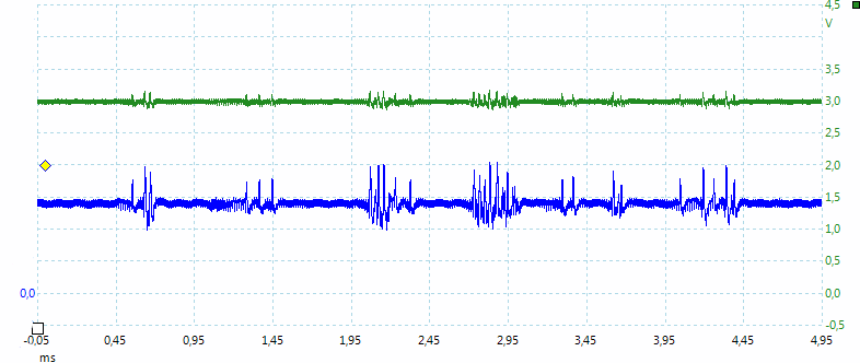
At full power with two batteries there is some high frequency (50 kHz) noise in the light.
Medium
The efficiency is better at medium leevel.
With a single battery the efficiency is very good.
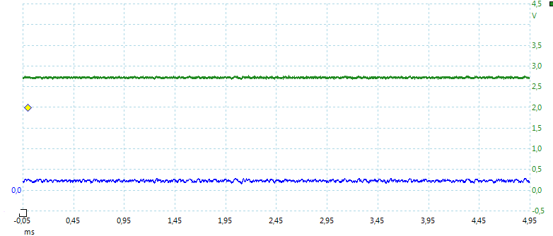
No pwm in the light, but some high frequency driver noise.
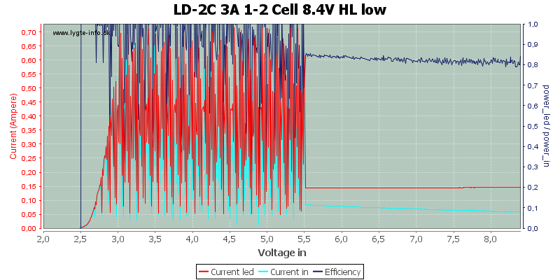
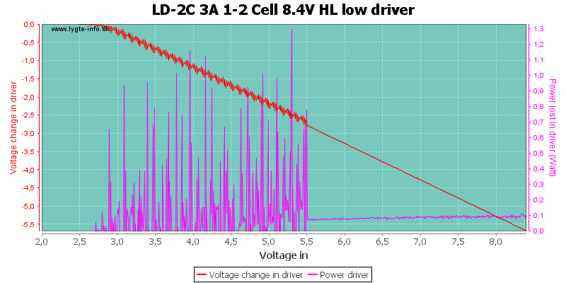
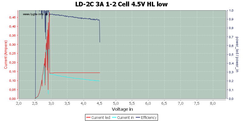
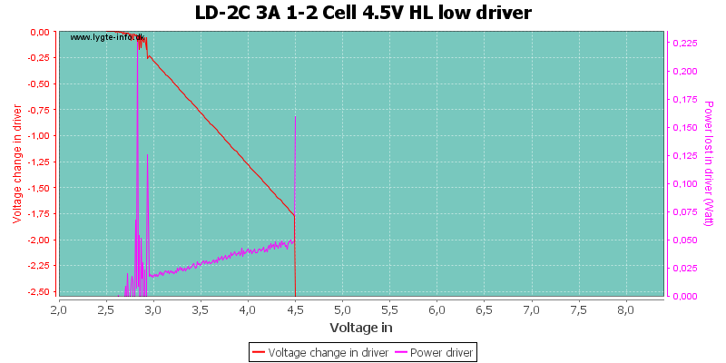
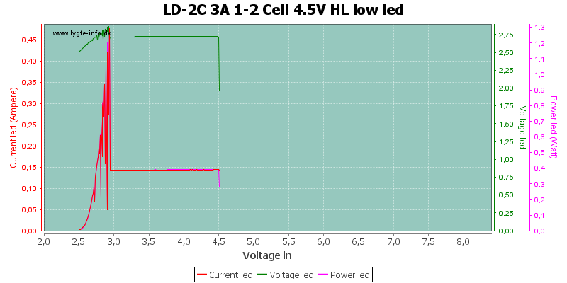
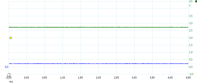
Low
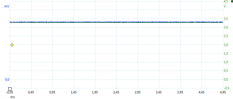
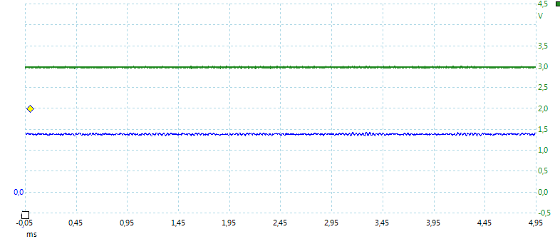
At low there is neither pwm or noise in the light.
Conclusion
The driver handles two different battery configuration in a nice way with low battery warning, but it does not turn off when the battery is low.
Generally the driver does what it is supposed to do, but I would like a better efficiency with two batteries.
Thanks a lot for this great review, for the time and effort you brought into this.
I fiddled around a bit with this driver by now and found 2 things.
The real life single-cell performance was quite low and lower than the chart suggests.
A fully loaded (4.2V) protected Panasonic NCR18650B (3400mAh) gave only slightly over 2.1 A at the emitter, measured with a 0.01 Ohm shunt. Second cell from same batch shows the same low current. The same setup with 2x NCR18650B in series gave 3.02 A emitter current.
Cells are 5 months old and got maybe 15-20 cycles. According to the 4th chart of HKJ this would mean an instant voltage drop to 3.5 V. Hmm… but that’s how it showed here. After the resistor mod described below (and assembled in a Convoy L2) I tried a single, fully loaded protected Sanyo UR18650FM (2600mAh) who has a bit more stamina than the Pana3400, and result is visibly similar. Can’t measure current any more in the light, but adding a 2nd cell definately increases brightness a lot.
Anyone else got the same experience?
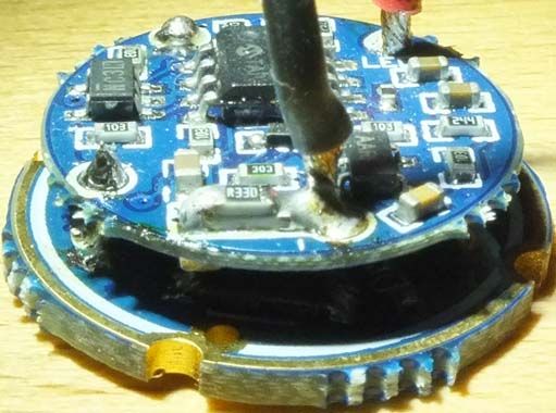
Second part is better: Resistor mod is a breeze on this one. I added a 0.33 Ohm in parallel to the “25LO” and this did increase from stock 3.02 A to 3.21 A (2 cell config, of course). See picture below.
Then I desoldered the added one and took 0.20 Ohm, this brought me to 3.32 A. Not really linear (should have been 3.38 then) but good enough. But current instantly - but slowly - dropped with heat: Within 30 seconds it was down to 3.25 A, blowing cool air brought it up to 3.29 again at once. Driver wants good heat transfer when even so slightly modded. I did not press further.
It fires an XM-L2 U2 1A on copper in 2-cell configuration now.
The picture with the 1st resistor mod:
I got a bored battery tube so I can run 3 c cells, 1 or 2 18650 cells or 1 or 2 26650 cells with a spacer, in this instance the lower single cell performance will be fine as I’m going to be using store bought alkaleaks in a pinch, and the better single cell runtime will be a boon rather than a problem, thanks for the review hkj.
Another great, thorough review. Thank you HKJ! For the price, seems like a pretty nice driver.
EDIT: I don't know about you, but I prefer low voltage warning only. Better to be told the cell or cells are low, but still have light than to be involuntarily plunged into darkness. I guess the best would be auto shut off that can be manually overrode every x number of minutes.
I’ve been doing some research, and it seems like the TrustFire Z5 has about 20-21mm of room between where the driver rests and where the emitter must be placed.
The original driver is 20mm tall, and is under driven. Makes sense, b/c the LED is pretty much resting on open air in the factory setup. If I cut the driver height down by half with this LD-2C, I can get a chunk of copper thermally expoxied in the bored out head. Heat management should be loads better, and then I can use a star smaller than 32mm—which just makes everything more convenient!
Thanks for the review, HKJ—you just helped me pick out the perfect driver for my upgrade
I started work on adapting an ATtiny13A to a similar LDCH driver, the LD29, but have not gotten around trying to finish that work. Here’s that thread: here is the LD-29 MCU pinout (eg how to put your ATtiny13A in there…). I think that there is plenty of information in that thread for a modder with a strong interest to actually complete an LD29 project using a standard ATtiny13A firmware.
I think it’s fair to assume that the same thing could be done with this driver. It could even be using the same pinout for the MCU - but just as easily it might be a bit different.
EDIT: if all you want to do is completely remove LVP there may be a voltage divider that can be modified to just pull the MCU pin “high”. If you want to look for that just measure each pin with a DMM as you adjust the input voltage. We’d then just trace the pin back to the divider and remove the resistor that goes to GND.
I know this is an old thread but I wanted to give this a bump and see if anyone else has had good results tuning this driver. The reason I ask is the next batch of Convoy L2 will use the LD-29. It’s going to come with a single cell tube and an extension for running 2 cells.