The circuit may not behave as intended with the two inductors being mounted in close proximity. You might want to pick out a driver with a shielded inductor or adjust their orientation to minimize coupling.
It’s not about paralleling buck drivers, but I had a thread that lead to discussion about paralleling 7135-based boards:
As mentioned in that thread there are a number of threads from awhile ago about “master-slave” arrangements, but I think that they were also about 7135-type drivers, rather than buck (or boost or buck/boost) type drivers.
This one (or any of the quite similar versions from LCK-LED or IOS, lightmalls etc)
Comfy, or anyone. You are pretty sure those drivers could do it if you remove the MCU and wire them correctly. Im most likely interested in using the LD-29.
[quote=M Stee]
The circuit may not behave as intended with the two inductors being mounted in close proximity. You might want to pick out a driver with a shielded inductor or adjust their orientation to minimize coupling.
[/quote]
Sorry for beeing a noob. Inductor=toroid? Which means, the larger thing with the wires around it? :)
You'd have to probe the MCU pins and find out which is the PWM output, then jumper that over to the slaved non-MCU board and hope there isn't other stuff on the board that needs the MCU to work. Though, I guess if you had to, it would work with all the MCU pins connected to the slave, effectively one MCU in parallel with two PCBs.
Some drivers just can’t be paralleled. I have know idea about the two you linked.
Unless someone has done it, you may have to parallel the drivers for yourself to be sure.
So... it gets the less-than-100% modes through pure analog control? Neat!
...however I think that's a case of using 'no PWM' as shorthand for 'PWM at a high enough frequency that it's not apparent to the human eye'.
edit: No matter HOW it does it, there still has to be an output pin somewhere that controls the component on the board that limits the output current to achieve the different modes.
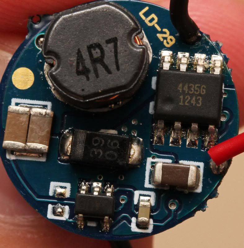
I’m pretty sure that MCU closest to the center of the board reads 12F683 on the LD-29 board.
Comfychair is probably correct. It’s listed as having a “low voltage warning” which would be controlled by the PIC12F683, assume the modes would be also. Now if you just knew which pin for the PWM.
You can parallel two single-mode constant-current buck drivers. Multi-mode too, but make sure they don’t have mode memory otherwise they could get out of sync with each other.
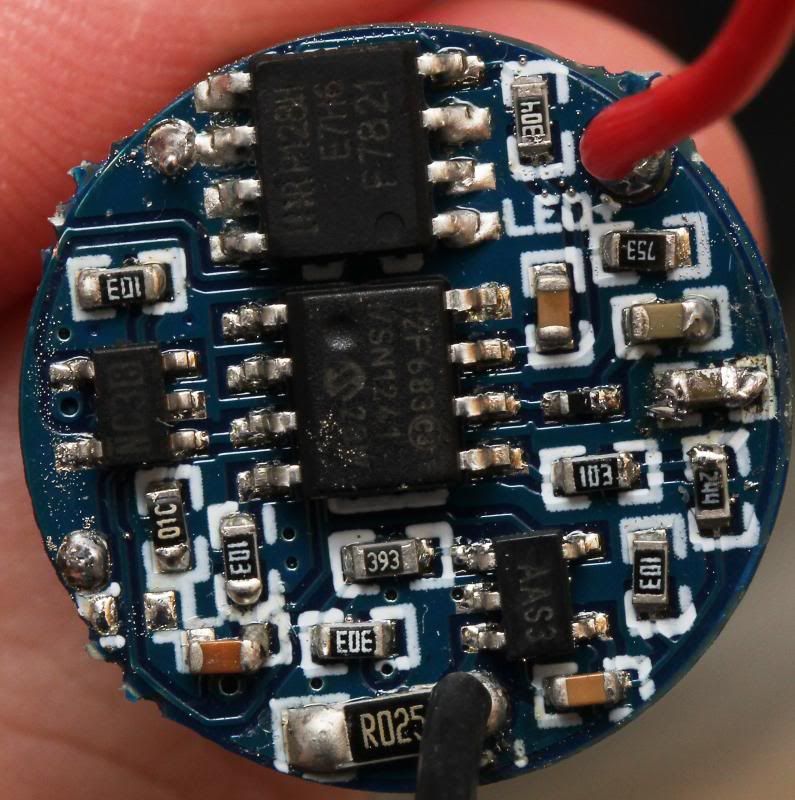
“4435” and P128H are both FETs, the former is P-channel, the latter is N channel.
“NC38” is the high side gate driver for the 4435, P128H is driven by the uC.
“3906” is the catch diode, handles the output current during the time when both FETs are off.
“AAS3” is a current sense amplifier, sensing the current in the negative lead of the LED by amplifying the voltage across R025. Presumably this goes to the PIC.
“AUB” is the voltage regulator for the PIC.
So the buck PWM is generated by the PIC itself, in software, based on the current measured by its ADC. Which means that you can’t master/slave the thing without losing current sensing.
Your best bet is probably to hot-rod the thing for more output current. To accomplish this…
- Change R025 (25mohm) to a smaller value, eg 12mohm for 2x current. Or stack another 25mohm resistor on top of it.
- Remove the 4R7 (4.7uH) inductor, because it’ll probably saturate and pop the LED. Find a 4.7uH (or higher) through-hole inductor with a RMS current rating at least 25% higher than the set LED current, and saturation current at least 50% higher than the set LED current.
Run the driver in open air, make sure it doesn’t overheat. If it does, you’ll probably end up replacing the FETs also.