I have seen the driver change mods, but I do not want to go buy a driver for this light. Especially when I can't seem to get any orders out of China any more. Everything I have ordered in the last 30 days has not ever come and I don't want to loose any more money or time.
Could there be a resistor change for the stock driver that would yield some improvement?
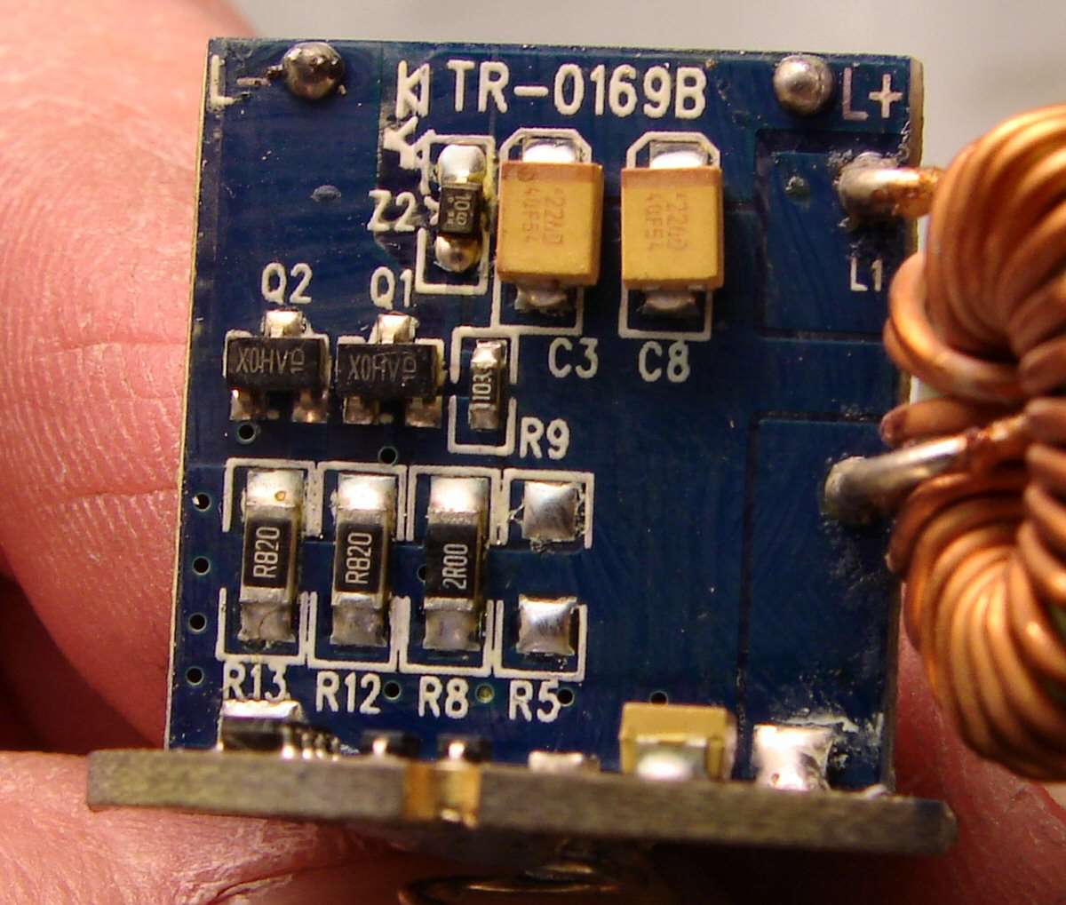
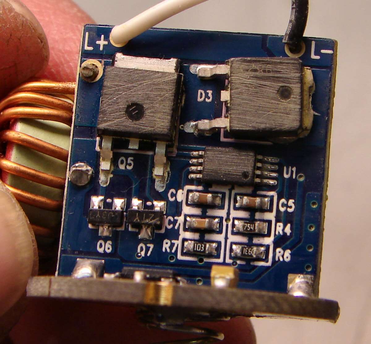
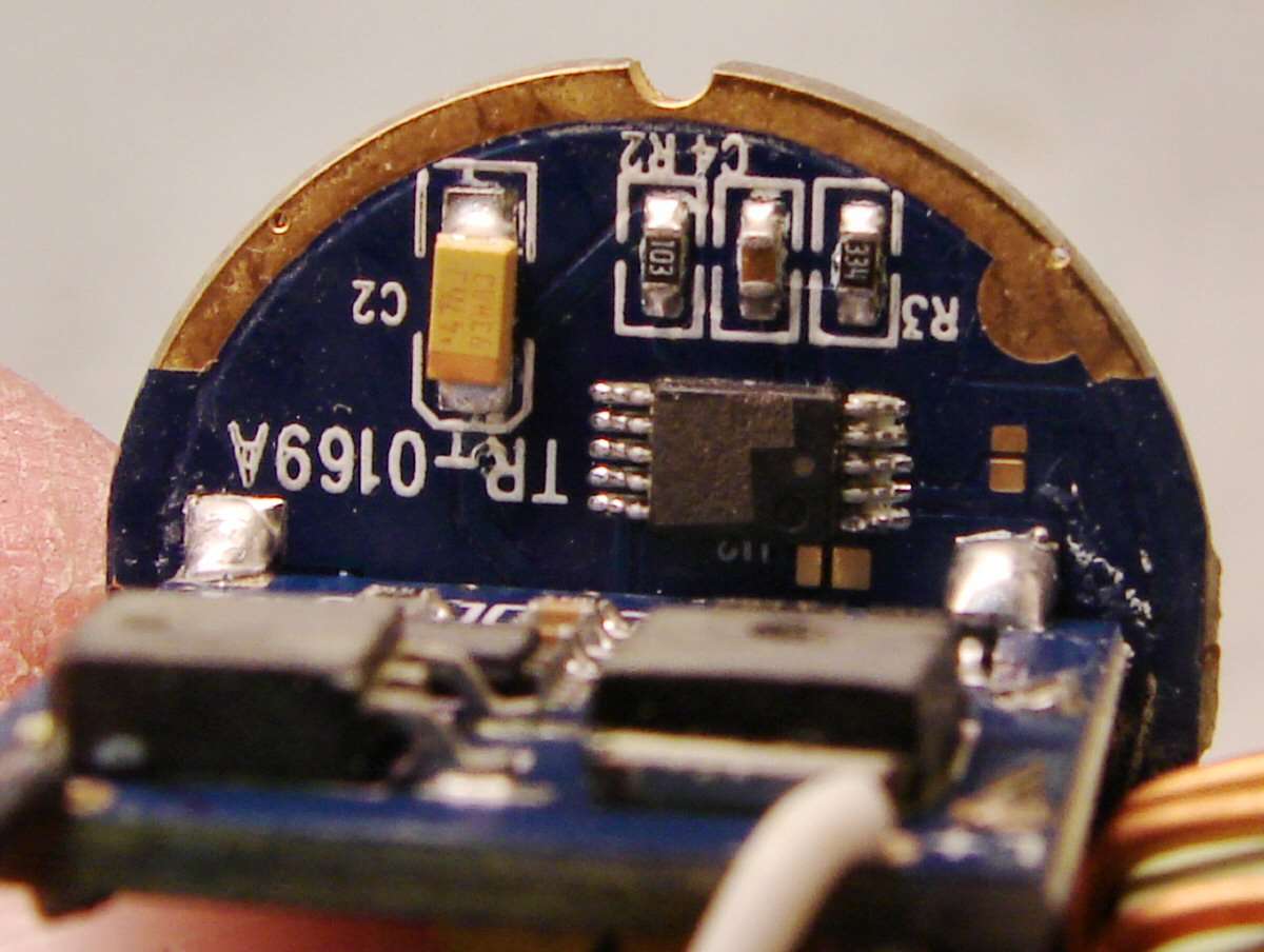
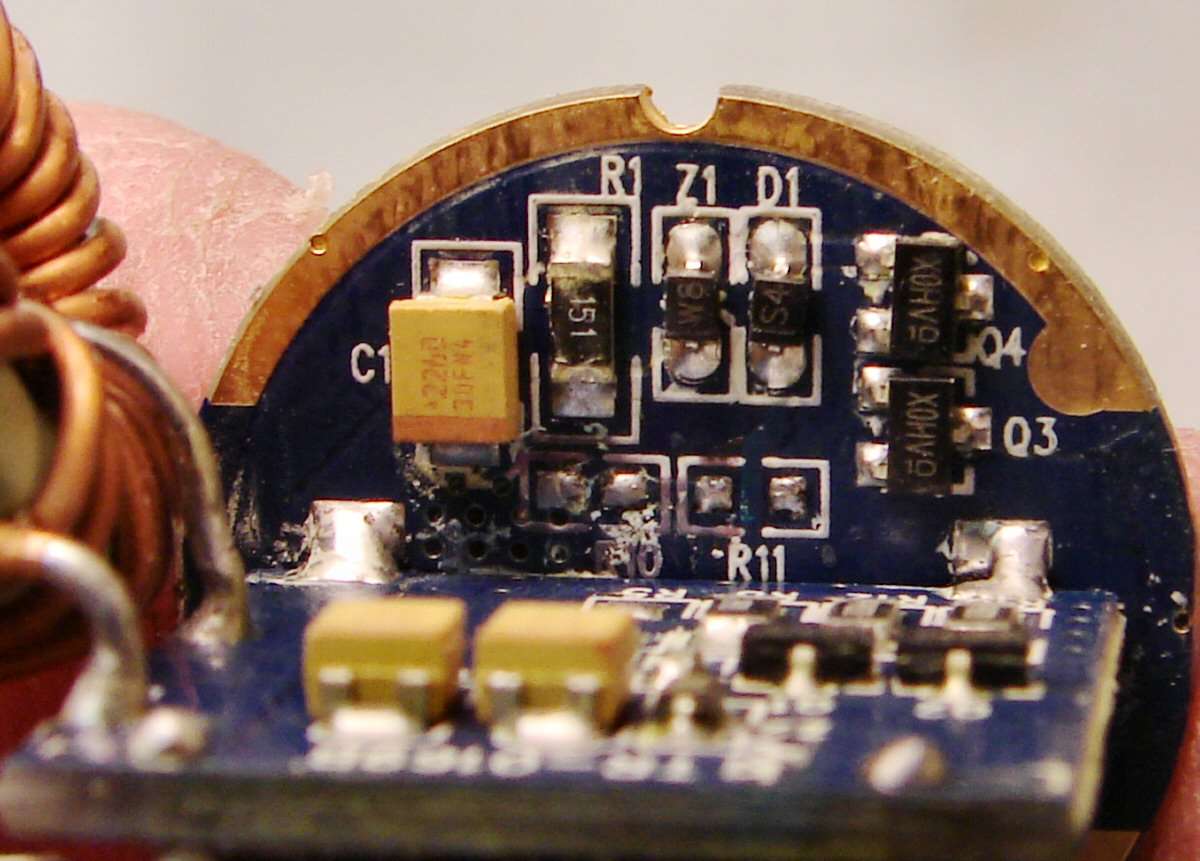
Photos of this driver, best I can do.
Cropped and edited to show the whole base driver without the upright board. Why? I don't know...
On those places you will see resistors with the following writing on top of them:
R820- R820 -2R00 - empty/no resistor
(0,8 ohm - 0,8 ohm - 2 ohm - empty/no resistor)
Those are most likely the sense resistors, all are in parallel (you might want to measure that they are in parallel just to double check).
On R5, the empty spot, you could add say an R900. If you want higher current add a lower value. An R900 should give you a good increase though. But I don't even know what this driver does stock..
As with all resistor mods that have not been tested. The lower the value, the higher the current. The higher the current the higher chance of destroying it... Some drivers does not mind a resistor mod, some does and can not be pushed that far. So if you follow this advice, do it at your own risk.
You might find this thread relevant despite that its a different driver circuit...
Well, I see from reading threads here, that the driver gives different values from 2x 26650, 3x26650 and even 4C batteries, so I can only say that my plan was to use 2X26650/18650, which should give about 4 amps, 4.5 amps from what I read in the threads, like this thread., which has a lot of info on what people were getting for amp draws. I did not read amp draw with 3x26650, because I wanted to go with two and cut the body down.
in his kind of drivers, input current always higher than LED drive current. because it step up voltage to higher than input voltage. other way, input power = output power + convertor loss
to measure LED drive current, you need to disconnect a led and connect amp meter.
actually you dont need to do it now. simply add between 1.0 ohm to 0.68ohm resistor to exiting sense resistors. then check for any improvement. large current increase may not be possible without changing drive FET or add another FET parallel.
Since the FET is only providing a path to ground, why would adding another FET in parallel increase current?
Or, are you just saying that if he WAS able to increase current, the existing FET wouldn’t be able to support that much current going through it (the existing FET), so he’d either need a different FET that could support the higher current or put an additional FET in parallel with the existing FET to split the current between the existing FET and the new, additional FET?
2 FET’s in parallel shares the load between them, so they together could switch higher currents. The rds is also reduced, the same way two resistors in parallel have a lower resistance. So with a lower rds together, a higher current could be achieved with more current handling capacity. If they where the exact same 2 FET’s basically half the rds of one and twice the load capable.
. . . large current increase may not be possible without changing drive FET or add another FET parallel.
This is a huge. Many of us have run across drivers we can't realized the desired level of current when even shorting the resister bank. Heat may be an issue, but at least the parallel FET would be sharing the current load .
Finding a compatible FET may be a challenge. Many have the identification labeling ground off by the manufacture. I guess one could find a compatible FET by measuring the physical size of the driver's FET and the voltage differential across the voltage sense resister bank. Do you have any FET recommendations that would likely work in most drivers. It seems that most are the same physical size (whatever size that is) and use a sense current somewhere in the range of .2 to .3 volts.
Thanks Moderator007. Sounds like a promising candidate. One of the SRK driver variants out there uses N channel FETs too. So maybe that FET is similar to what is used in most drivers.
Speaking of FET's. The ones in the first picture of the OP were poorly seated. Probably connected good enough though.
Looking at a SRK driver (version with a large capacitor and one inductor coil). It has two N channel FET's, but I can't tell if they are wired parallel. My labels are ground off, but GTamazing has one too and his is labeled as follows:
DTU
06N03
DD13U
I think the one I have reads over 6 amps at the tail.
Well, I'm not having much luck finding .68 ohm or .82 ohm 0805 resistors around here. I even tried ebay us sellers. Nothing unless I want to go to a kit for big bucks. I don't have anything at home except for a couple R200 here, which won't help and I don't even know for sure if it will do what I want. I'm about to just use five of the NANJG drivers and call it a day, with a shortened tube and one of the Sony 50amp 26650 batteries. 15+ amps, that ought to fry eggs in a few seconds, in that light.
I just don't want to order from China. I've got a hundred bucks worth of orders already aiming for 45 days from, several sellers and nothing can be tracked and none of them want to refund, so I will have to go the paypal route soon, so no more orders from China.
Right now you are at .34ohms resistance. If that gets you to 2 amps, the voltage differential is about .68. So adding a R200 will get your resistance down to .126 and your current to the emitters up to 5.4 amps.
Do you know the size of your R200 resistors? If they are 0805's, they can only handle 1/10th of a watt and would not probably be able to be used in place of the other resistors.
EDIT: If you want to be safer, you can first remove the 2 R820's. Then you would be at about .18 ohms resistance and 3.75 amps current. The best way for me to remove a resistor is to use a blob of solder that touches both ends of the resister. It usually lifts off with the soldering iron.
I can't tell without measuring, but the 3 resistors share the current. So each gets 1/3 of the total current going through them. They should be bigger because 1.36 watts (.68 volts x 2 amps) is going through that bank (if driver is delivering 2 amps stock).