**Update Jan27, 2012**
(Cleaned up the post a bit and added xp-g data)
Gentlemen,
Here are my results from testing the Cree XM-L emitter(s) up to 5 amps.
**Update Jan27, 2012**
(Cleaned up the post a bit and added xp-g data)
Gentlemen,
Here are my results from testing the Cree XM-L emitter( up to 5 amps. This is something I've wanted to do for awhile now, mostly because I haven't been able to find this info on the interwebs, and partly because of some debate and speculation going on in a few recent threads. This test took a heck of a lot longer to do than I first thought, so without further ado here are the results:
Test Set-Up:
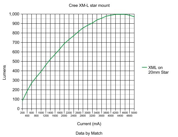
* Emitter tested: Cree XM-L 1C mounted on a 20mm star
* Sample Size: 8 chosen randomly out of 80 (all I had the patience/time for)
* Test rig: Stars mounted on 1lb 25mm pure copper barstock set into a ~10lb block of pure aluminum. Arctic Silver 5 used on star.
* Temperature just under star monitored entire time. Maintained +/- 1 Degree throughout testing.
* Results taken 10sec after power on for any given level
* I know it's obvious, but lumen results are emitter lumens (bhp, not rwhp for you motorheads)
Here's a few pictures of the heatsink and test set-up:


And now for the big table and graph. The following represents the average results of the 8 different emitters for each data point (All emitters were within <1.1% of each other...another reason I stopped after  :
:
| Current (ma) | Lumens |
| 100 | 40.31 |
| 250 | 104.3 |
| 350 | 147 |
| 500 | 207.1 |
| 750 | 303.5 |
| 1000 | 392.1 |
| 1400 | 520.9 |
| 2000 | 686.2 |
| 2400 | 773.1 |
| 2800 | 852.2 |
| 3000 | 881.4 |
| 3200 | 905.9 |
| 3400 | 937.5 |
| 3600 | 956.5 |
| 3800 | 977.1 |
| 4000 | 988.9 |
| 4200 | 996.0 |
| 4400 | 996.8 |
| 4600 | 996.0 |
| 4800 | 988.1 |
| 5000 | 973.2 |
6-24-2011 Cree MC-E test added:
Mr. Oldbobk was kind enough to send me both an MC-E and an SST-50 to test. Test performed is exactly like the xm-l above, except only one emitter was tested. I will update again with sst-50 data once that test is complete.
| Current in ma | Lumens |
| 200ma | 73.5 |
| 400ma | 142.3 |
| 600ma | 207.1 |
| 800ma | 267.2 |
| 1000ma | 323.3 |
| 1200ma | 376.2 |
| 1400ma | 424.5 |
| 1600ma | 470.4 |
| 1800ma | 513 |
| 2000ma | 553 |
| 2200ma | 596.8 |
| 2400ma | 630.8 |
| 2600ma | 661.7 |
| 2800ma | 693.3 |
| 3000ma | 718.6 |
| 3200ma | 746.2 |
| 3400ma | 768.4 |
| 3600ma | 788.1 |
| 3800ma | 808.7 |
| 4000ma | 826.1 |
| 4200ma | 837.9 |
| 4400ma | 849.8 |
| 4600ma | 861.7 |
| 4800ma | 868 |
| 5000ma | 874.3 |
| 5200ma | 869.6 |

6-30-2011 SST-50 Test added:
Again, same test set-up as for the xm-l. Here are my results up to 6.4 amps, which is as high as my bench power supply would go.
| 200ma | 61.3L |
| 400ma | 122.8L |
| 600ma | 181.8L |
| 800ma | 239.5L |
| 1000ma | 294.2L |
| 1200ma | 348.6L |
| 1400ma | 400L |
| 1600ma | 449L |
| 1800ma | 497.2L |
| 2000ma | 543.1L |
| 2200ma | 587.4L |
| 2400ma | 630L |
| 2600ma | 670L |
| 2800ma | 708.3L |
| 3000ma | 746.2L |
| 3200ma | 790.5L |
| 3400ma | 825.3L |
| 3600ma | 857.7L |
| 3800ma | 889.3L |
| 4000ma | 921L |
| 4200ma | 948.6L |
| 4400ma | 975.5L |
| 4600ma | 1001.6L |
| 4800ma | 1026.9L |
| 5000ma | 1047.4L |
| 5200ma | 1056.4L |
| 5400ma | 1067.2L |
| 5600ma | 1087L |
| 5800ma | 1110.7L |
| 6000ma | 1126.5L |
| 6200ma | 1146.2L |
| 6400ma | 1160L |
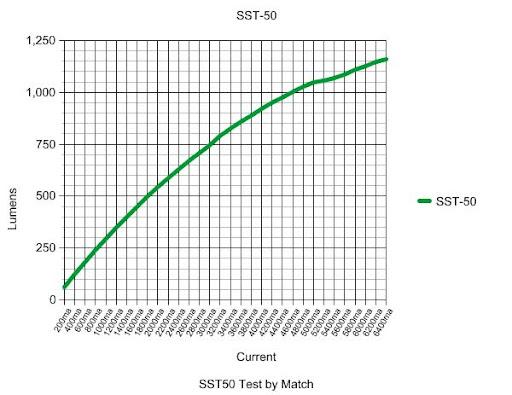
And there are the results. I didn't notice the drop around 5200ma until just now, but can attribute that to being distracted at the time and may have gone past my 10sec lumen snapshot. My data is rather more conservative than what is stated by the official datasheet, and that could be contributed to any number of variables. For example, even though my test heatsink is monstrous I feel that the 20mm star itself is the bottleneck for heat transfer. It is interesting to note that where the XM-L falls on its face at any current past 4.2amps, the good old SST-50 keeps chugging along. In certain high draw applications this would definitely be beneficial, not to mention the bond wires are much thicker and more numerous vs. the xm-l.
That's it for now...Considering all emitters were tested under the same conditions and with the same equipment, this should hopefully provide a good comparison between them. I hope some find this info useful.
Thanks for your time,
- Match
*Added Jan27, 2012*
Cree XP-G R5
| 200ma | 80.9L |
| 400ma | 154.2L |
| 600ma | 218.2L |
| 800ma | 274.3L |
| 1000ma | 322.5L |
| 1200ma | 365.2L |
| 1400ma | 398.4L |
| 1600ma | 423.7L |
| 1800ma | 442.7L |
| 2000ma | 453L |
| 2200ma | 454.5L |
| 2400ma | 446.6L |
| 2600ma | 430.8L |
| 2800ma | 403.2L |
| 3000ma | 364.4L |
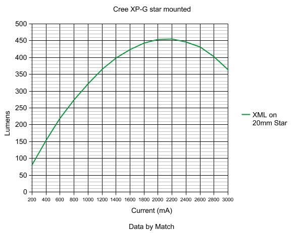
For your viewing pleasure, the Cree XP-G. Test set-up was the same as the xm-l above (except only one emitter tested).
Special note for the morbidly curious: After the testing, I decided to sacrifice an xp-g by seeing at what particular amp level it would let out the magic smoke. I kept increasing current at 200ma increments past 3 amps (roughly 3 seconds between steps) until *poof*. The answer is 4.2 amps. I don't know about you, but I was rather surprised!
Enjoy,
-Match
Update April 28, 2012
Many of you have requested that a test be run on the Cree XR-E R2. Thanks to Dthrckt who was kind enough to send me one, those results are now in. Again, testing procedure was performed like the others above.

Seeing as how the xr-e's are primarily used for throw, the above graph shows why such great sucess in this endevour is seen at greater than stock current draw. What my testing only indirectly shows is the increase in surface brightness that's critical for extreme throw.
Also note that this emitter was tested as shipped mounted on a 14mm(?) star. Life's been rather hectic as of late, but I plan in the near future to test this, along with the xm-l, directly mounted to copper. I believe it will be possible to get over 400lm out of the xr-e, along with a substantial increase in throw, in this configuration.
As always, thanks for reading.
-Match

