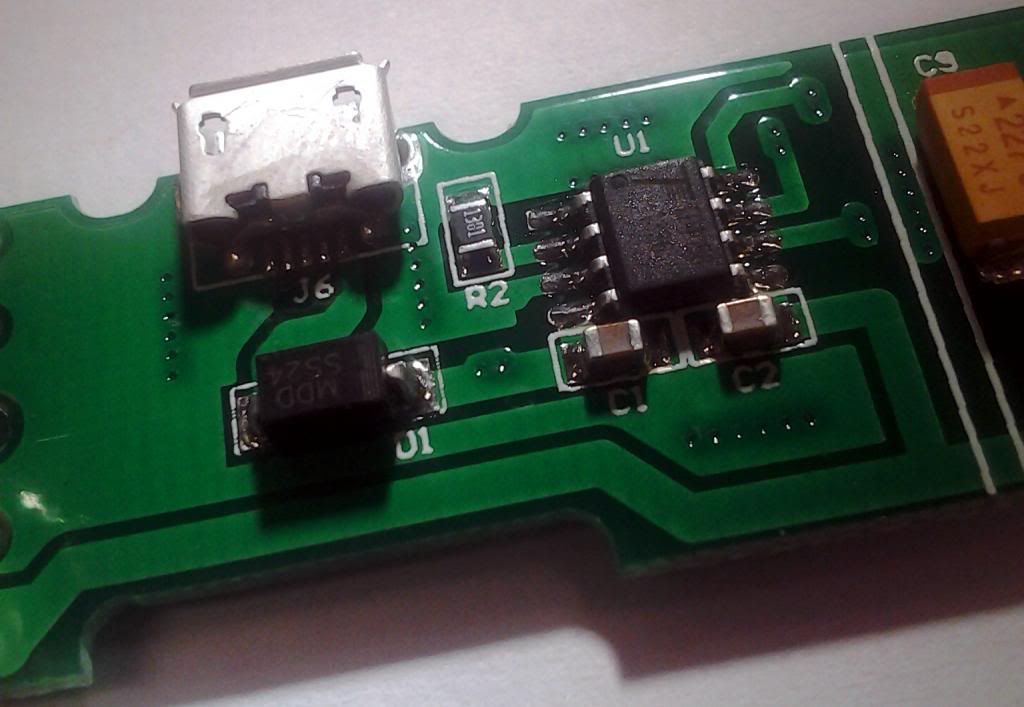
Well I have been eyeballing these TP4056 USB micro USB PCB modules, well wouldn’t ya know it…on my MC1 it fell off my desk and the micro USB connector on the PCB broke…so I opened it up to investigate…found a chip inside that had 57b8 on it (the charge controller chip)…couldn’t for the life of me find that IC…until now. Found the TP4057, which in the data sheet…has 57b8 all over it! This data sheet is mostly Chinese, this one is better
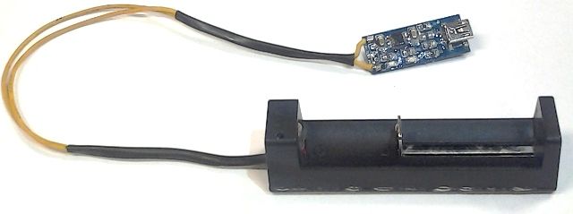
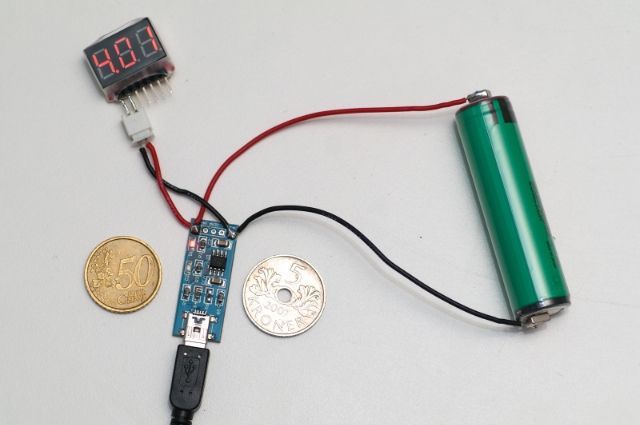
So in effect the EXACT same thing that runs the MC1 by Xtar (some of the BEST Li Ion chargers out there) with some wire, some tiny neodymium magnets you could in effect build you a charger like this
or with a cheap single cell battery holder like this
Oh yeah...soldering it back on for sure...but wouldn't mind having a DIY project and pump out a bunch...especially since they are alot better than the TP4056, which is good...
TP4057 has been used in a few chargers. Original ml-102 used dual tp4057 too.
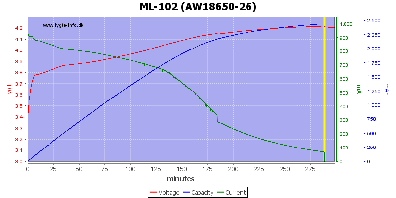
Why do you see it as better then tp4056? TP4057 doesn’t seem to have a solid CC phase, current starts droping nearly from the start. Not bad for batteries but it is slower. TP4056 on the other hand does give a real CC phase. HKJ ml-102 review.TP4056 review.
Note that the ml-102 curve is a 2600mAh cell and the tp4065 is a 3400mAh. Extra 800mAh and its still faster.
Are you planing to repair your Xtar MC1? Seems like a nice design. Slider. Plug at the end so a couple can actually used side by side (unlike the ML-101 / 102). Though they advertise it as compatible with 10440s when the current is too high.
no need to, 500mA~ current, doesn’t get hot at all…plus I use it as my spare charger at my desk at work (I have a Nitecore i4 at home [along with 5 Miller ML-102’s V6’s modded to 500mA charge as portable power banks for the kids kindles])…so if I need to charge one of my vaping batteries, (I do carry spares) I keep an eye on it
Now that you mention it…daggumit I shoulda used some clear heatshrink…dangit
Great post war hawk. I have bought several 4056 boards over the last few days and was wondering what to do with them. My specific concern was attaching the batteries to the wires. How do I do that properly, without a short, also where do I get neodymium magnets?
Wonder if you could attach a 6V 300ma solar panel?
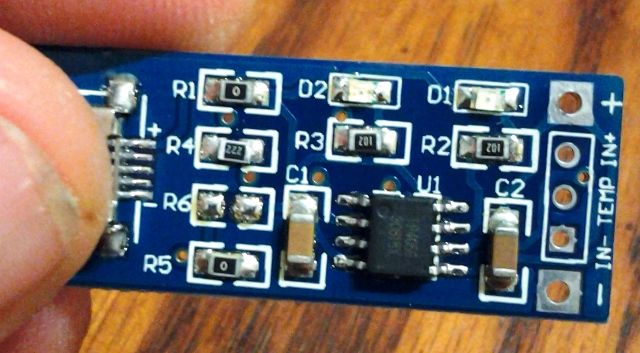
Not sure what Mountain King was asking, but the place to connect + , - to battery is marked on board I believe.
It would be very cool to put in a host. How would you put it in a host BTW? How would you put a charge circuit in and keep it waterproof and not risk having short circuits?
I got 3mm neodymium magnets from FT, just can’t solder to em…the heat kills the magnetism
I’m thinking some sort of electrically conductive epoxy would be best to bond the wires to the magnets
This is why I saved the housing and sliders of the MC1…inside the housing where the positive and negative terminals just tacked down the leads going to the TP4056 and then soldered the other ends to the USB module making sure polarity was kept of course, then heat shrunk and voila
Pot it into the head with only the ports showing. In the past I’ve made a wax casting then a mold to cast the circuit in to make it removable. For the length of this I might need to add a finned section for it to be useable with a custom pill reflector.
Well…killed my first TP4056 charger module the other day (oh well…out $1.15)…might need to put a Schottky diode inline to prevent reverse polarity, but if I do that, the voltage drop across the diode will end up make it undercharge the battery…one simple slip of the mind and not paying attention and kaput.
Oh and yes, the clear heatshrink tubing works AWESOME at covering the little board!
.png)