I have a need for charging protected Trustfire 10440 for my Tank007 E09 as well as other small LiIon batteries. Until now I used 0.5 A to charge them but that is too high current. I wanted to be able to pull a battery early based on the falling current in the end phase (constant voltage phase). A voltmeter would be a poor indicator in that phase so I decided for an AMP meter.
I bought the following which all came after fourteen days.
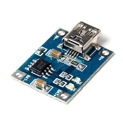
A charger print with TP4056:
http://www.fasttech.com/products/0/10005926/1453504-tp4056-1a-li-ion-battery-charging-module
A cheap charger with a spring mechanism to hold the battery:
http://www.fasttech.com/products/1421/10002785/1207600-universal-single-slot-lithium-battery-charger
And an AMP-meter to show how charge is progressing:
http://www.ebay.com/itm/DC-0-To-999mA-Red-LED-Panel-Meter-Mini-Digital-Ammeter-/130949465473?pt=LH_DefaultDomain_0&hash=item1e7d324581
The TP4056 board:
Charging from USB: (the charging stops when the AMPmeter shows around 20mA, after that it shows zero)
The charger print had the TP4056 (without logo) and charges with true CC/CV. I changed the current resistor to 4K7 to get 0.25A
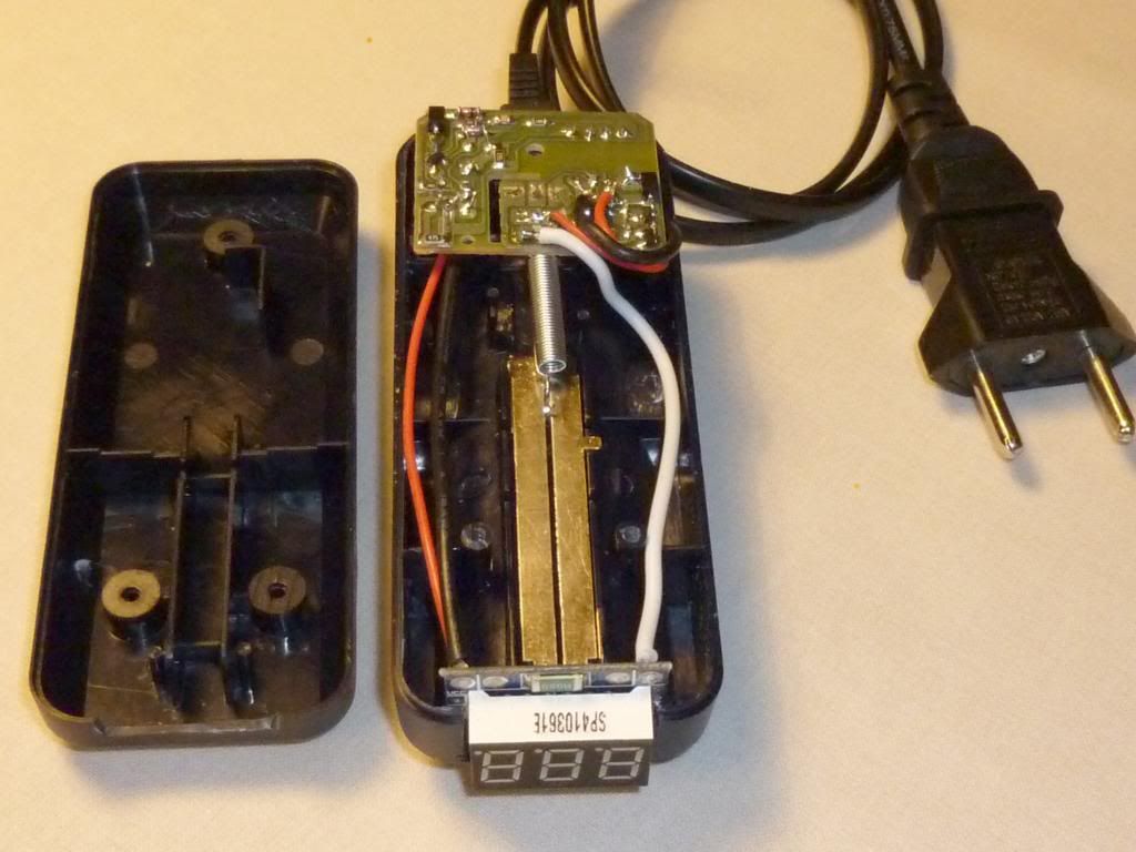
My first intention was to rip the single slot charger completely and mount the new charger print in the empty space.
Of course, before that, I tried the single slot charger on its own to see how it did. It is marked 0.5A and started charging with 0.43A falling to 0.32A at 4.0V. As it reached 4.264 V while still charging 0.23A, I stopped. This IS cheap.
But this charger produced 7V, suitable to drive the TP4056 and had space (barely) for the TP4056 print if I removed the large indicator LED. So I decided to keep the rest so I could also charge from the mains.
Here I found space for the print, the mini USB going through the case:
Here beneath the original print:
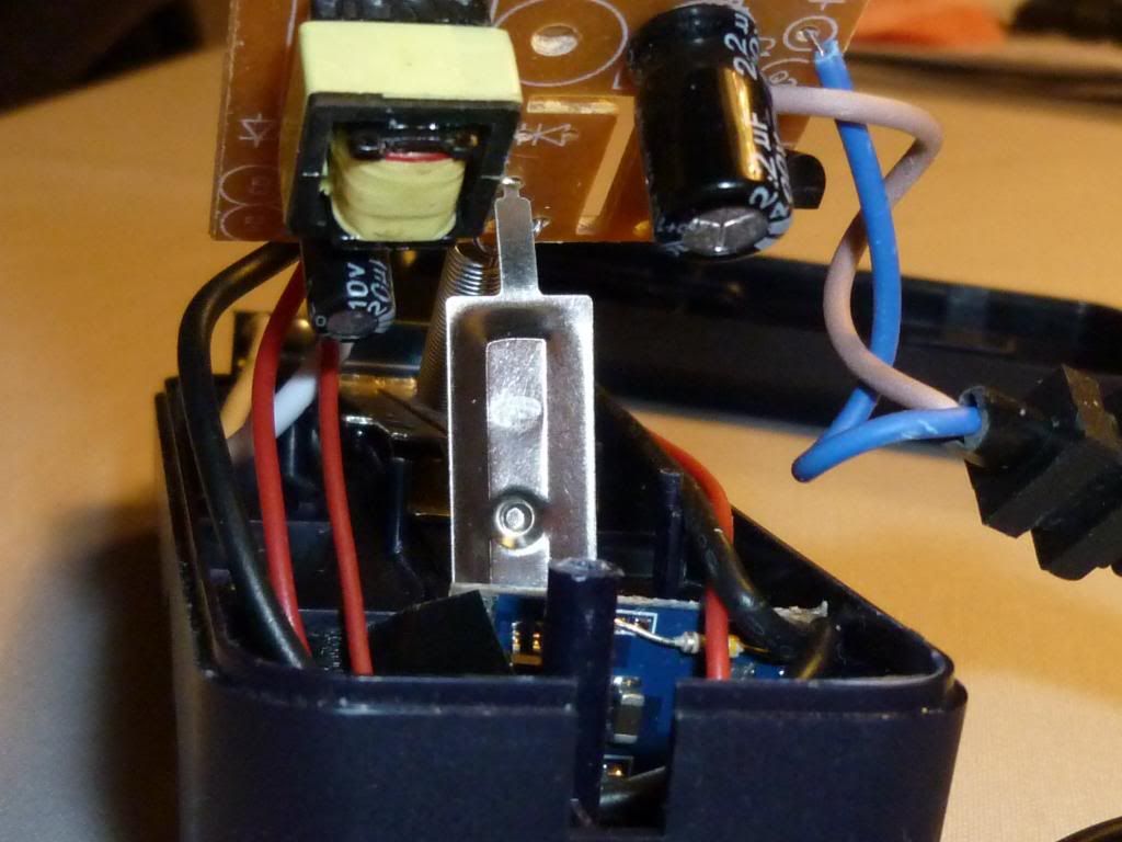
The mini USB going through the case:
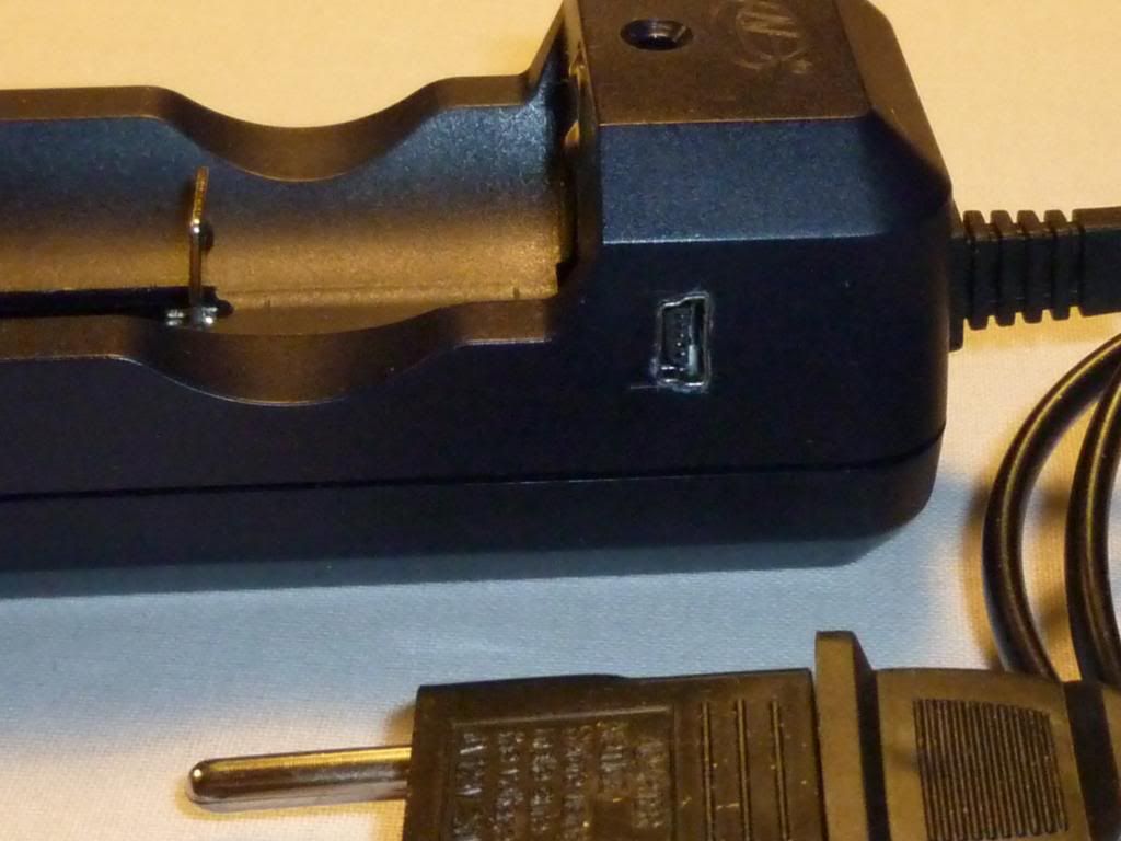
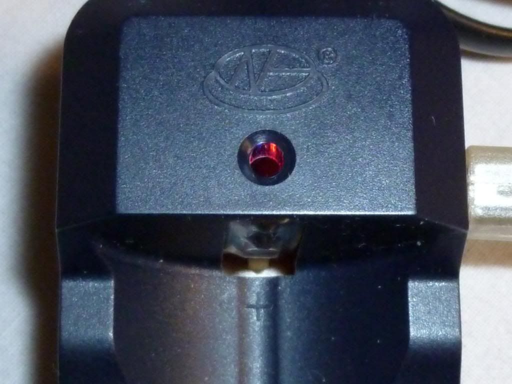
The small indicator lights shine faintly through the original hole:
Before closing the bottom:
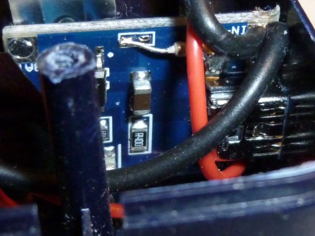
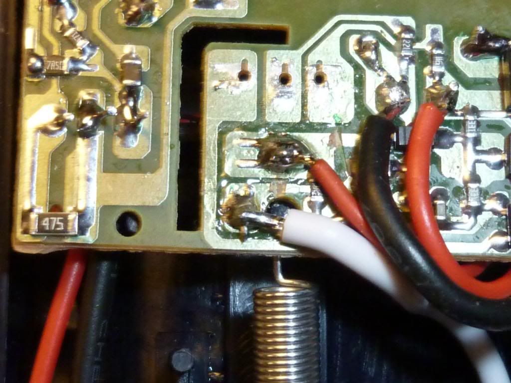
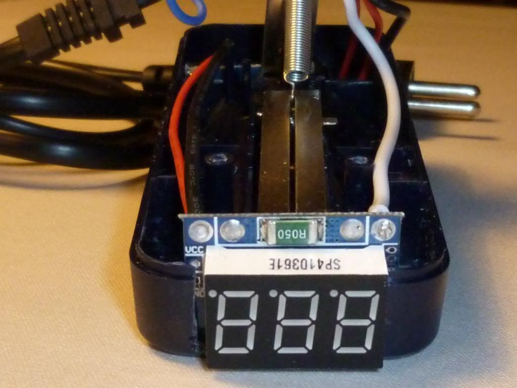
A closeup with empty holes from the old indicator LED and cables to 7V (to the right) and to the plus post and minus spring (traces cut to theese):
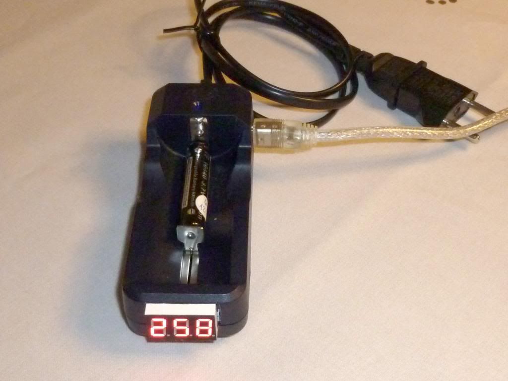
The AMPmeter:
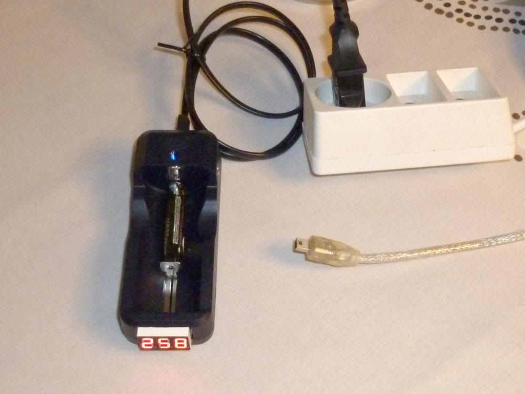
Charging from the mains:
Further development:
A piece of acrylic rod over the indicator light could enhange the visibility, but never mind, I have the AmpMeter.
I could put in a switch to change the current resistor for 0.5A charging.
