2014 Scratch Build Entrant - Handmade - Failed

UPDATE: I regret to report that I will not be able to deliver a completed build. I have no excuses. I can say that I did give it my all (given constraints fom non-hobby responsibilities). I think my biggest lesson was that it is generally best to stick to an initial plan. I burnt a lot of time thinking up new ideas and adjusting the initial plan to accommodate them.

I would like to express my gratitude and thanks to Old-Lumens for creating this contest last year. I have learned much from participating and have picked up some new skills along the way.

I would also like to thank the other participants and BLF members that gave me valuable advice and words of encouragement. The true spirit of BLF shone bright during this contest. This place is quite unique and special. Thanks SB for creating this forum and for setting a great tone from the top.

I also would like to thank Illumination Machines for providing me a sample of their CST90 reflector. I regret not making the contest deadline. I will get the light working and report on the reflector's performance soon.

Finally, I would also like to thank the sponsors that have donated prizes for the winners. Your
generously created a more exciting contest.

Best wishes to the remaining participants!


___________________________________________________________________

"I feel the need, deep in my soul, to rage. I want to rage against the darkness and the night with all my might." - MPD, at some future date

Hi, my name is MPD, short for Multiple Personality Disorder. Besides being big for throw and endurance, I'm meant to be modular for easy future upgrades/mods. Some features I will have if finished by the contest deadline are as follows:

  • A central emitter for throw.
  • Multiple emitters to the left and right of the central emitter for floody throw
  • Mulitple high current drivers using momentary switches for the emitters to separately control the emitters for various levels of throw and flood.
  • The emitters and drivers will all be on one large copper plate with only one positive power wire and momentary switch wiring to disconnect for removal. Oh, and 4 mounting screws.

Some of the features I will eventually have, but probably not in time for the contest deadline are as follows:

  • Shorty battery tube
  • SRK type high CRI tailcap light(no one will sneak up behind my handler)
  • Asperic head attachment
  • Lantern attachment
  • Two dedomed XP-L's mounted in a "V" or Teepee formation to get maximum intensity to the reflector surface and to create a relatively compact intense, high lumen output central light source. Don't know it will work, but I will be attempting it soon.

So I'll eventually be a thrower, a floody thrower, a flooder, and a lantern.

___________________________________________________________________

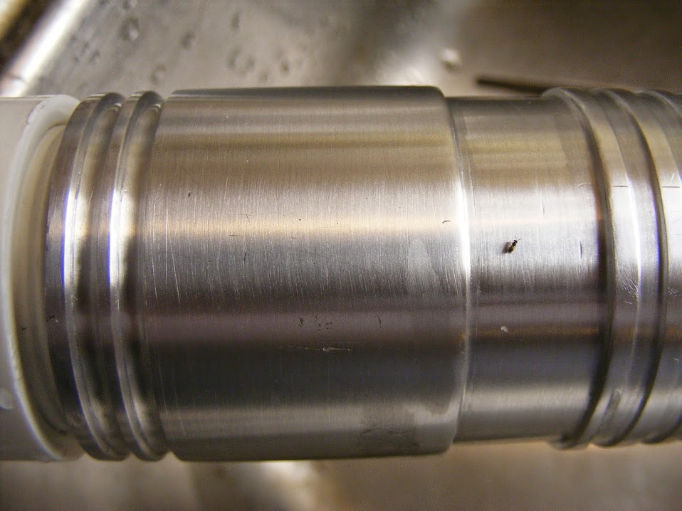
This light is not meant for comfort, although I really like the battery tube diameter. I find it quite easy to hold and grippy due to the ribs. It will probably be front heavy without the "SRK" tailcap light, but I don't mind that. The primary goal I have for this light is to maximize the following

  • Heat sinking
  • Throw
  • Run time
  • Versatility in an outdoor environment

Here is a sketch to get an I idea of what I'm shooting for. The tube may be longer depending on driver choice. The reflector portion of the head will be longer. Still debating about having a handle. Also thinking about a different tail configuration. I like the size of the tube, but my wife would probably want a handle. The head will be about 5.25 inches (133mm) in diameter. This will help with heat sinking to handle a hard driven emitter.

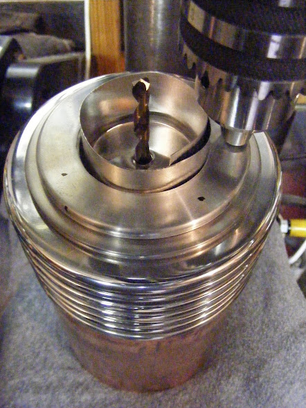
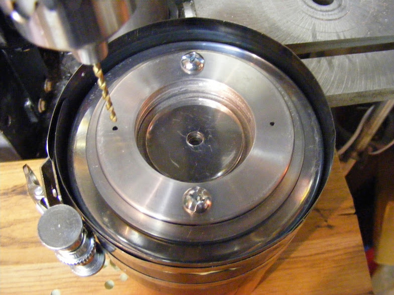
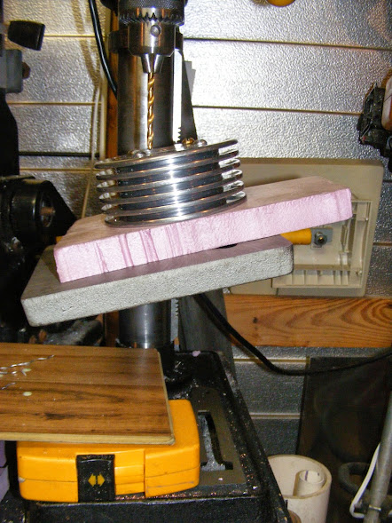
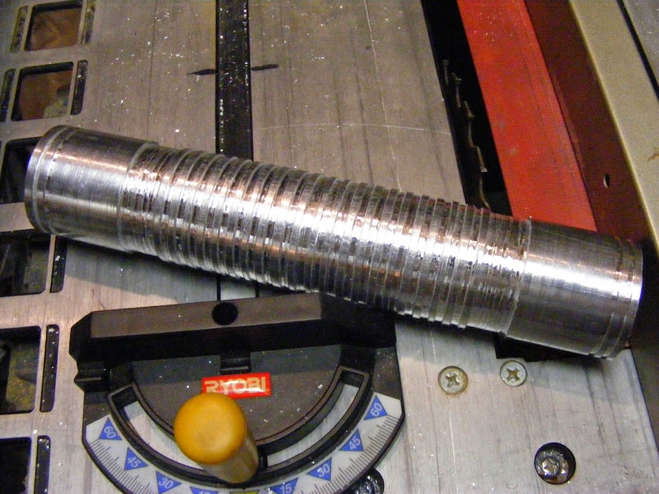
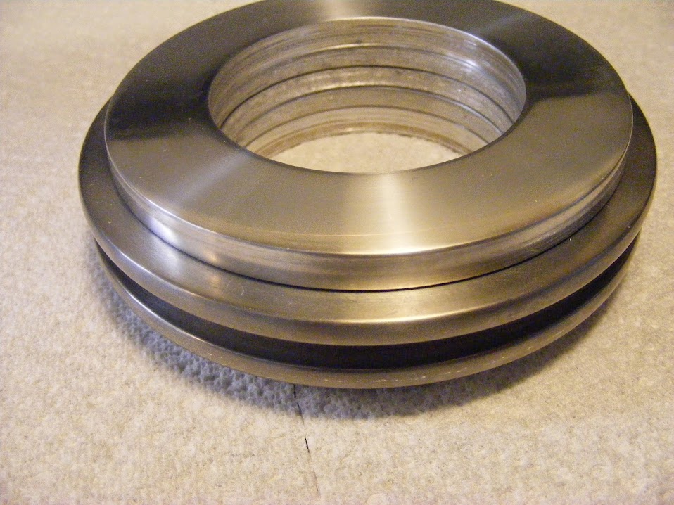
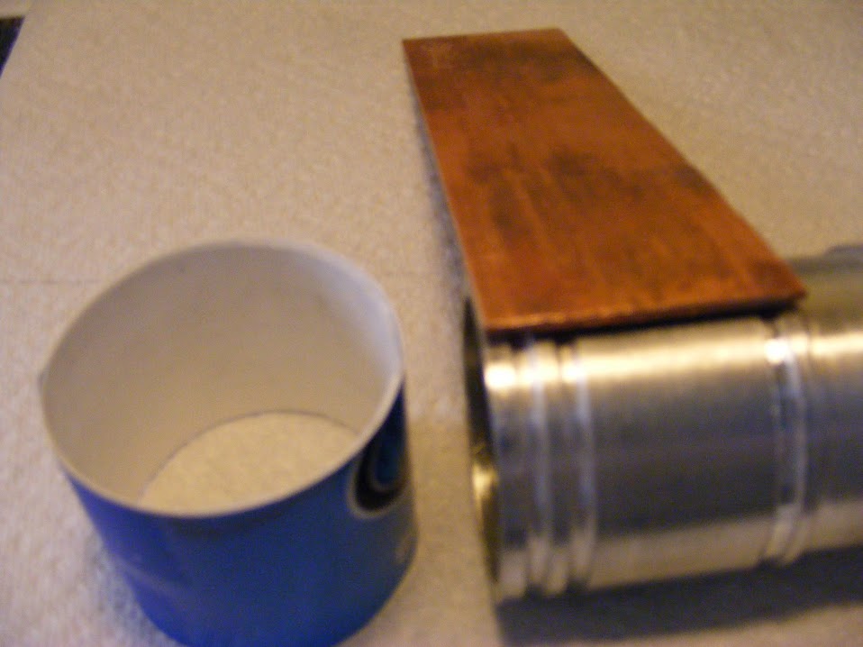
The upper head will be built from copper. The cooling fins for the lower portion of the head will be made out of 6061 aluminum disks with a copper round bar through the center to transport the heat from the emitter to the individual disks. The primary battery tube will hold as many as 12 18650's, but the light can run on just 2 cells with a spacer, if needed. Will have a side switch.

Some parts are laid out in about the length that the light will likely end up being The ABS coupling is there to get a sense of the size that the head. To give a sense of proportion, the smallest cooling fins are bigger in diameter than the bezel of the T90 in the picture.

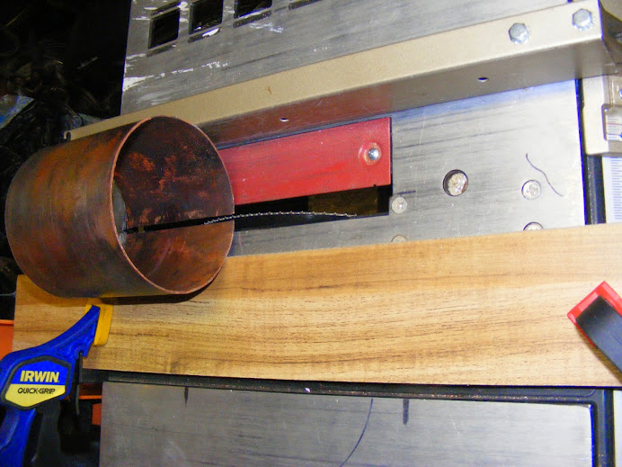
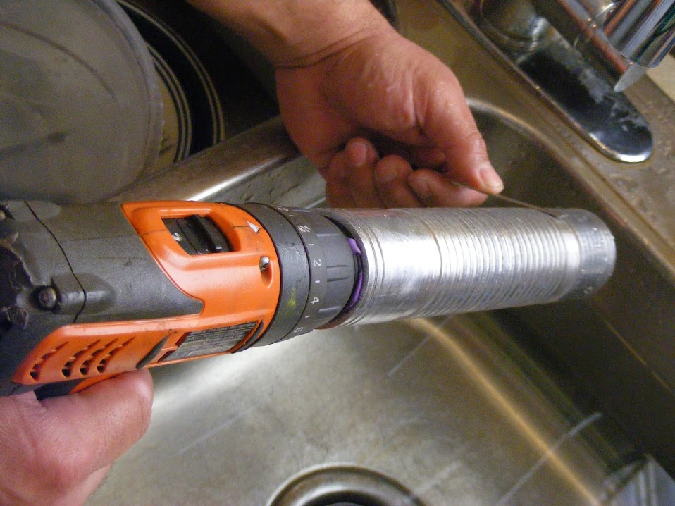
The biggest challenge will be the head. A 5.25" diameter aluminum tube is very expensive. I will fabricate that part of the head. Another challenge will be the large size of everything on the light. It will make many of the tasks such as polishing more labor intensive and awkward. There are some other challenges that will even be worse if I have the time to include a couple surprises I would like.

Thread Organization:

  • OP - General info
  • Posts:
    1. Materials Used
    2. Head
    3. Battery Tube and Carrier
    4. Lens and Tail Cap
    5. Emitters, Drivers, Switches (oh,my)
    6. Miscellaneous
    7. Failures

Purchased some aluminum from my local Metal Supermarkets. Got a discount because these were leftovers from cuts for other customers. They don't just give a discount. I had to point out that they would not have to cut up any new stock and that I would take the whole of the two remaining pieces below (I have cut out some disks from it in the below picture). The plate is 1/4" 6061 aluminum. The tube is 2" (5.1cm) OD and 1/8" (3.2mm) wall thickness and type 6063 alloy. I really wanted matching materials to help have more consistent results with anodizing, but cost would be too high that way.

Got the reflector I wanted and scored some 1 1/2"ID (38mm) used copper pipe from a landscaper on Craig's List. Wall thickness is .07" (1.8mm).

Reflector:

I didn't want to reveal the reflector until I could show it in action with a couple of ideas I have, but time is running out. The reflector is the CST90 from Illumination Machines. Those folks make amazing products. I tried to get a group buy together one time for this reflector, but got no traction.

This reflector is a defect, has some dents and some dull spots from sanding/cleaning or something. It was the best I could get from IM as I could not commit to buying a minimum 100 units. I have played with this reflector by hand and can tell you it is an impressive thrower. I got close to 300kcd with a dedomed MT-G2 driving around 11 amps. I have some interesting emitter plans, but I need the basic light completed to try them out.

Nuts and bolts that will hold almost everything together:

So folks don't have to scroll all the way to the end of a post, I'm placing the stages (subsections) in reverse order. So generally, my most recent progress will be at the top of a post. The details under each stage will still be in chronological order. So recent progress for each stage will still be at the end of each stage.

Assembly:

Getting close to assembling the head. This picture gives a general idea of the head. It doesn't include the anti-roll device yet, which will also serve as a shoulder harness point and future mounting point for a handle. The reflector's OD is a good bit wider than the copper section. So the head will step out to a wider diameter at the end and should have a copper bezel holding the reflector and lens in place. Not sure if I will be polishing the copper. I kind of like the contrast of the used, repurposed copper to the polished aluminum. The picture below doesn't do it justice for some reason. Not all aluminum pieces are polished yet in the picture below.

Staging up to drill 4 holes through the mounting plates, heat sink fins, copper portion of head. Using a scrape of aluminum flashing to keep the mounting plates centered.

To help keep everything in alignment for the drilling, I'm using a piston ring compressor. I have used this tool several times in this build. Before this build, the last time I used it was to help with rebuilding a 400 small block chevy engine that I put in a Pontiac Fiero. That was a fun pocket rocket of a car. I wish I still had it.

Reflector:

The reflector is designed for a specific light of some sort. So I have to cut it. Used a diamond disk to cut the bottom flat. I need a big opening for my plans.

Cut went well. More to continue once the basic light is completed.

Reflector Portion of the Head:

Had to cut a very long peace of copper pipe for making the side wall for the upper part of the head.

The same procedure described for other parts of this light was used to split and flatten the copper. I then used a 4" PVC pipe and a piston ring compressor to help get it to a true shape.

I cut the piece over sized just in case. Used a table saw to take out strips as I stepped it down to its final size.

Here is the piece after the seem was brazed. I brazed from the inside. This is the first big piece I ever brazed. Had to use a #4 tip with the output fairly high to braze it. It's not a pretty braze, but I get it now and will do much better on my next braze (which will be attaching the bottom). I now know, but biggest problem in the past was not using enough heat. I will actually be using even more heat next time. That large copper piece just sucks away the heat at an amazing rate.

Checking with square indicated I had a problem.

Closer inspection revealed the piece had shifted while brazing. Did several alternating passes rotating by hand on a table saw to true up the tube as best I could.

Base of Reflector Portion of the Head:

Splitting 1 5/8" (4.13cm) OD copper pipe to spread it flat. Did this by hand for a while and then realized there had to be a faster way. Mouse over is finishing the cut with a sawzall.

This thick old used pipe is stubborn. Had to anneal to make easier to spread out flat. The annealing process burned off much of the the tarnish and dirt. Dropping in water caused the remaining to "shatter" off. Came out of the water looking new. Mouse over is this piece spread "flat" will need another annealing and flattening session. Placing between to flat plates and pounding flattens the best for me.

Here is the base piece after the first flattening.

Its since been sitting under weight between to iron plates and is dead flat now. Cut into a circle shape and partially lapped. Didn't want to bother with full lapping as the surface will oxidize a bit and warp when brazed. Here is the upper head pieces ready to braze together. Mouse over is after braze and some clean up.

Here is the outside of the assembled head. Debating if I want to polish it. Since it is from old reclaimed plumbing, it has many deep scares that will likely not come out without making the wall way too thin. I kind of like the rustic look and it should improve as it naturally patinas.

Lower Portion of Head (Main Heatsink):

Cut out the disks out that will become the heat sink for the lower part of the head. Picture below is setting up for a 5" (127mm) disk to be cut out. Mouse over is a couple of the battery tube fins being cut out. Cut most of the depth for the outer cut circle, then cut inner circle while the piece is bigger and easier to hold.

Here are the disks that will form the lower part of the head. They have burs and don't lay flat yet. The 5" ABC coupling is just to help me get a sense of proportion as it is about the size of the reflector's OD. The reflector is about 2" longer. The battery tube will have a smaller set of fins.

Deburred the center holes and then sanded flat (mouseover).

Put bolt through the center hole and secured with a nut and lock washer. Then put in a hand drill (mouse over).

Used wet sand paper to shape the disks.

For the bottom fin, cut a channel using a 2" hole saw blade. The channel is for the battery tube to rest in.

Smoothed channel with a diamond file on hand drill again. I actually due it under water to keep the file from clogging up. Sized it for a light hand press fit. So just a tad bit tighter than snug.

For the 2 fins that will hold the head to the battery tube, I ground out a camfer that will press against o-rings. The o-rings will press in to groves in the battery tube. It will provide a very strong waterproof joint.

The fins ended up being different diameters. So I found a long bolt and attached them to the drill together. Then used 320 grit to bring them all to the same size.

Polishing. Man, its hard work. I tried to use the drill, but it caused more problems then it was worth. Ended up having to hand polish all of them. Started with 320, then 600, 1200, 2000, Mothers Billet Polish, and then Renaissance wax. You have to spend a long time at each grit to get the right finish. Many, many hours. I think I could write a book on polishing now and I feel like I'm just starting to scratch the surface. Sorry, couldn't resist the pun.

Kind of funny, you can see the order I polished them in based on the quality of the finish. The ones in the back are the first ones. They get less shiny as became more tired and felt the pressure of time building. I guess I better consider the 2 on the bottom still in progress and revisit them with sandpaper, polish, and wax.

Battery Carrier:

For the back bone, I cute 4 strips from a 1 1/2" PVC tube using a table saw. You definitely need a dust mask for this as the fine particles are probably not healthy to breath.

Here is how they will fit in the battery tube.

Contact Plates within the Battery Carrier:

My main source for copper. 5/8" (1.6cm) OD copper pipe I got on clearance from Home Depot. .035" (.89mm) thick.

Split it and start spreading. Just used the tin snip to pry open. Then used a one ton arbor press to finish spreading and mostly flatten them.

Finish flattening with steel plates. Since I won't need them for a while, I just put them under and between the plates with a little weight on them. When I finally retrieve them, they should be completely flat. The copper piece on the top went through that process. It is the piece I annealed up in Post 2. If I'm in a hurry, I use a plastic or wooden mallet to pound the top metal plate.

Battery Tube:

Battery tube will be 10" (25.4cm) long which will give 2" (5.8cm) of driver space.

Cut the tube from 2"OD pipe using a table saw using an OSD blade. Blade did not have enough diameter to go all the way through pipe. So cut was made by setting the blade real low and rotating the pipe by hand over the blade. Also cut groves to make the tube more grippy the same way.

Made for pretty rough finish. Lots of filing ahead.

Started filing, but progress was slow. Portion to the right mostly done.

Put rubber bands around drill chuck and filing went faster. Mouse Over: Rubber bands made tube quite wobbly. Switched to vinyl tape and tube was much less wobbly.

Trued up tube ends on drill press.

2 groves on each end for o-rings. Top of the head will not be water proof, but I want the light water resistant from beneath the emitters on down. O-ring channels not yet rounded out.

Found PVC fitting that press fitted nicely into battery tube. No more wobble.

Yikes! A fruit fly or something is eating up my scratch build!

Wanted to do preliminary finish sand before installing cooling fins. Will be harder to handle after that point.

Used PCV again to hold battery tube fines for shaping and sanding.

Preliminary shaping and and sanding. Ready to press fit and solder to battery tube.

Lens:

130mm lens are expensive. I also need some other custom sized lenses. So bought some cheap glass cutting tools:

Don't know where to get AR coated glass yet. So using glass I have around the house for now. Tried to cut a real thick glass table top. Could not pull it off. Three attempts yielded broken circles. Also tried a glass door for an entertainment center, but it was safety glass and shattered when I tried to break out the lens. Here is the first attempt with thick table top glass before I destroyed it.

Ended up using some low quality home window glass. Splinters like crazy.

Tail Cap:

Learning from 2 tail cap fails (See post 7), I cut a longer piece of aluminum (from old tube of unknown alloy) this time and bored it out by slowly by rotating against that bit.

Doesn't have enough ledge to securely hold bottom plate (Will be copper). Cut a thin strip of aluminum that will be a very tight press fit when done. Rubbed soap on the strip to aid in monitoring temp for annealing.

Heated with propane torch until soap turned black.

Easy to bend afterwords.

But stiffens up after being manipulated. Re-annealed for final bending.

Making cuts in tail cap and in battery tube for o-rings that will hold the cap in place when using the light. Middle cut has the grove started for o-ring to rest in. The other 2 cuts will have groves too that go all the way around the tail cap. Grove made by rotating the cap over the table saw blade. Black marks are were the interior o-rings are located for water resistance and to keep the tail cap from rattling.

Works good with just one o-ring. To remove cap, turn 90 degrees and pull off.

Used PVC plumbing connectors and electrical tape to hold tail cap onto the drill chuck for sanding.

Ready to press in tail cap ledge, finish sanding, and annodize. Then press in copper bottom. Hard to tell in photo, but bottom 3/8" is smaller diameter.

To Do's:

  • Sand and polish interior of the tail cap
  • Finalize size of aluminum strip and press in to tail cap
  • Do final shaping of tail cap
  • Make copper bottom plate and polish
  • Final sand cap to prepare for anodizing
  • Anodize cap
  • Press copper bottom into tail cap

This will be the plate that the emiters and drivers will be mounted on. The same 4 nuts and bolts that hold the top head and battery tube on will hold it down.

Here is the mounting system I designed to hold on the battery tube. It uses 2 o-rings and flanges and 4 bolts. It works fantastically better than I imagined it would.

Opps, this shot was supposed to show the nuts in the head.

Tail Cap:

Had two tail cap failures.

First was an aluminum one:

Used a table saw with an OSB blade to cut a short piece off this old painted 2 3/8"OD aluminum tubing. The ID is a little less than 2 inches. So I will need to bore it out slightly to fit the battery tube. Not sure how I'm going to get the paint of it. It's tough and stubborn.

Cut bottom of cap from scrap piece of aluminum sheet. Doesn't need to be nice because brazing will fill gaps and groves.

"Final" Sanded outside of bottom plate and inside of the cap before assembly as it will be harder to sand after assembled.

Soldering bottom plate into tail cap. Mouse Over: Could not find my AlumaWeld. So picked up this stuff at Home Depot. Probably the same stuff.

Finished soldering. This soldering product didn't seem to flow well.

Once sides had been made true to get rid of all the rough gouges from the hole cutter blade, the bore would have been too large. Also the cap would have been too short for the type of securing mechanism I'm going to use.

Second failure was a copper tail cap:

Wrapped a layer of thin cardboard around battery tube to get a larger diameter. Then cut another piece of cardboard to fit over it. Used it to determine what length of copper pipe to cut out. Marked copper pipe with masking tape to provide a guide for the cuts. Used sawzall to cut. Should have used table saw.

Split pipe length wise. Used sawzall to cut. Should have used table saw.

Annealed and spread flat. Then cut along length to get height of the cap. The 3 grooves in the battery tube will have o-rings to prevent water entry.

Bent copper sheet around tube to shape tail cap.

Rolled copper while around the tube on a steel plate to get fairly true. Took several annealings.

After final annealing, used a automotive hose clamp to tight down on several spots along the sheet to get a final true up on shape.

Ruined cap trying to braze it together. I have never tried to make nice looking braze work. This does not bode will for the copper head I was planning on making. I either need to get good at brazing or make the upper head out of fiberglass. Fiberglass would be good from a weight perspective, but not for head shedding.

I like the idea of one big flashlight with mtg2. with one big reflector you will achieve apart lot of lumens but also decent throw. nice.
the battery compartment will need special attention I believe.
wish you luck.

A 13cm reflector will be suiting company for a MT-G2 :-) Looking forward to the build and the performance!

I have a name for you

“Last Dragon” because…

Yooou are the last dragon…you have the power of the glow

that or SHO NUFF!

hehe

:smiley:

Crazy reflector size! Where did you source that one? Or from what did you source it? Oh do tell! :-)

Looking forward to this!

Nice. I'm glad I'm not the only one that has no idea what he's doing. Good luck on the build.

Ervin Anastasi:

Thank you. I need it.

djozz:

Me too, if it works as planned.

WarHawk-AVG:

Dude, totally love your sense of humor. I just saw the movie for the first time a few weekends ago. I will admit that I could not stop watching it. The bad acting and cheesy special effects made me laugh, but on another level I really got into it. Thank you for that.

Ledsmoke:

All will be revealed at the appropriate time.

Old-Lumens:

Hope I don't let you down Sir.

MRsDNF:

You pegged that one right. I'm totally battling design paralysis on this project. I have a couple special ideas for this light, but they are looking more and more unrealistic by the moment.

I love that film man :bigsmile:

You’ll think of something. And if not, do what I do and borrow someone else’s ideas. In the end we all do that to some extent. What makes it different is how you adapt an idea to your project. On another note, you must have HUGE HANDS.

Pilchman:

Thank you. I felt a little exposed after putting it out there that I liked the movie.

Rufusbduck:

Hope your right. This build is forcing me to learn how to do several new things. It's beyond my current experience and skill level, but that's a good thing. For that, I thank O-L for creating this competition.

Average hands. A bit wide and thick from decades of tinkering and working on things. The battery tube is M6 sized (SRK without the exterior lands cut out).

Looks like this will go down in the history books of insane MT-G2 mods! :)

Goliath’s flashlight :smiley: