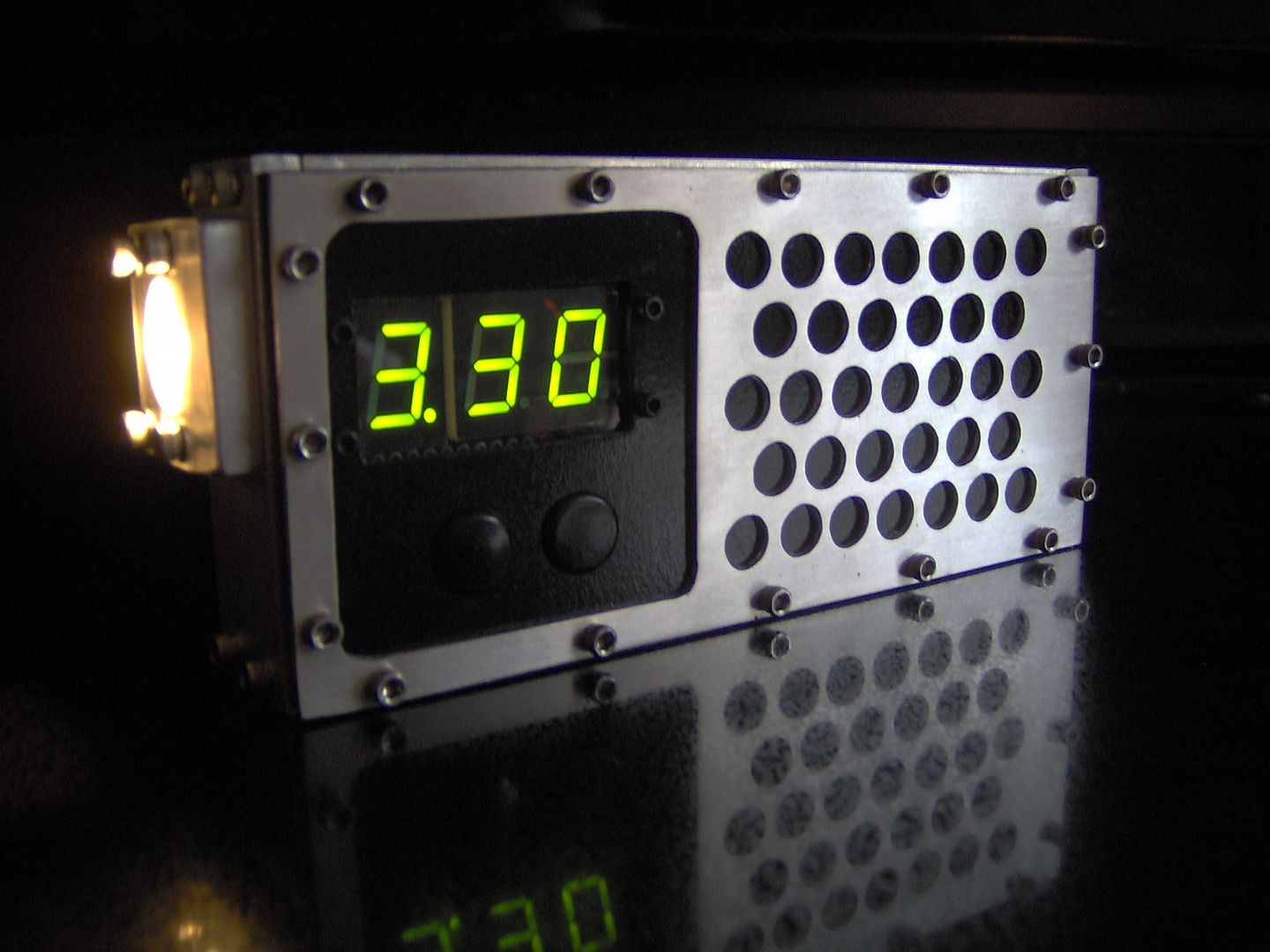
Here is the final Trim of the Solar Rechargeable FlashLite (2014 BLF Handbuild Contest)
In the Beginning:
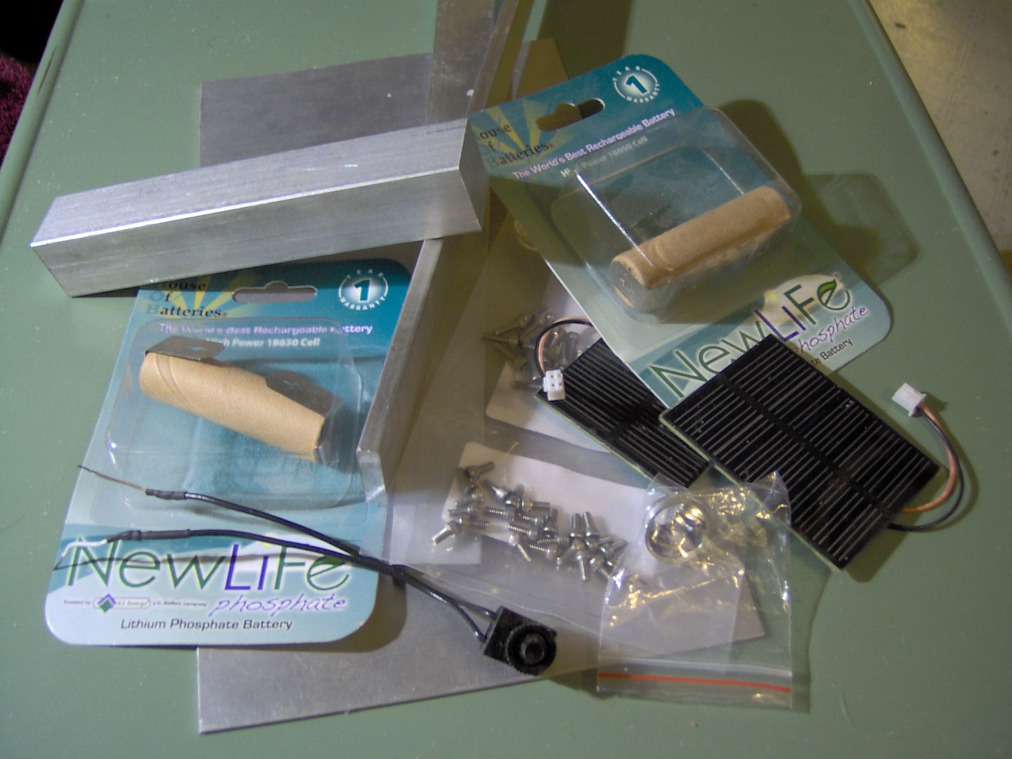
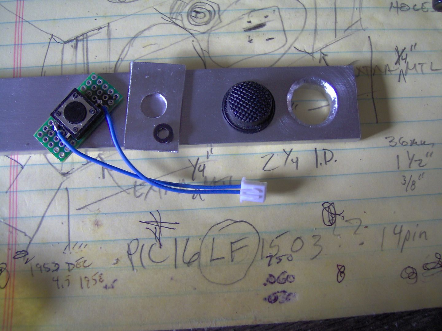
Here is the pile of materials. It’ going to be a solar rechargeable light (Free Energy) ![]() . A couple of 18650 K2 LifePo4 batteries, FET direct drive, Hi CRI XML-2 led, 7segment voltage indicator, two button switch thingy. At least that is the hope.
. A couple of 18650 K2 LifePo4 batteries, FET direct drive, Hi CRI XML-2 led, 7segment voltage indicator, two button switch thingy. At least that is the hope.
Now as OL says, GET GOING!!!
First off, is the AL bar frame that was handsawed, so nice pretty mating edges, ha, ha . At first I was going to use the sawzall on it ( because it was going to be allowed this year?), but didn’t have the right blade. No straight holes, or tapping because, they are hand-drilled. This project is more about function for me, call it industrial design, or whatever.
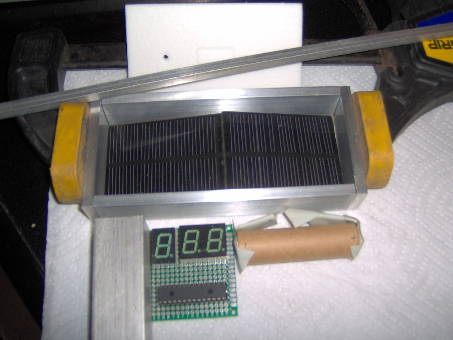
Next pic is a mockup of the 1” x 1/4” AL bar frame. I originally was thinking of just face mounting the mini solar panels to a back-plate, that in turn was also face mounted to the AL frame, and then picture framed with some 1/8” abs sheet to hide the edge. Now I’m looking at doing an inset job, if it is feasible, for a couple of reasons:
1. I couldn’t stand the thought of getting down to the last drill and tap of holes in the AL bars for the faceplates, and have an accident, like breaking off the tap :_( . That would just about mean a complete redo.
2. It is only going to take a little sanding, or filing, the two mating mini panel edges to get a nice snug fit. Still have to have a back-plate, but precludes the need for the abs trim. And, if something goes wrong with the faceplate mounting, I won’t have to redo the frame, because I’ll be screwing into some inset 1/4” tube, or angle.
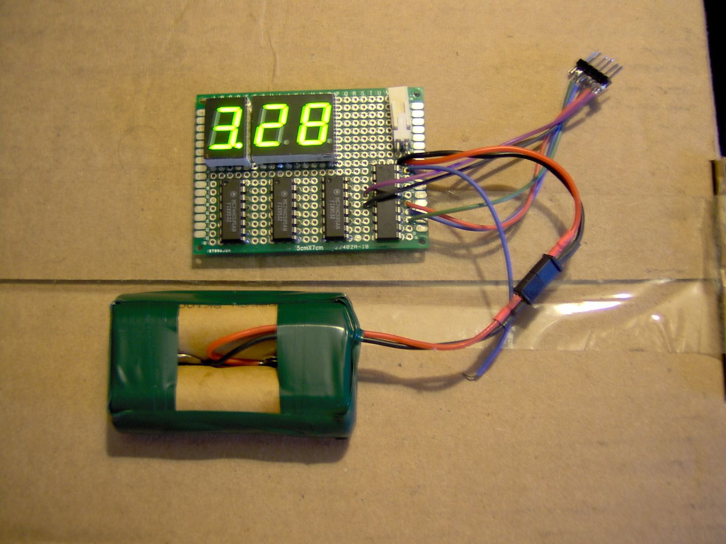
The electronics are going to use a multiplexed 7 segments that I scrapped from a satellite receiver that was found in the local recycle/scrap metal pile. I may still buy a proper 3 digit common cathode one, because it would actually be cheaper than to buy some 2V Vgs (because of LifePo4 batteries) pfet’s to source the common anode displays.
About the only pfet part number I’m coming up with, that’s in a TO92 pkg. (no SOT23’s thank you), is something like a Zetex ZVP4105A http://www.digikey.com/scripts/DkSearch/dksus.dll?Detail&itemSeq=147381264&uq=635325857287589608 Unless someone has a lead on another pfet, low 2V Vgs, TO92 part they like to use? I have some BS350P’s but their Vgs threshold is too high at 3.5V.
After trying to solder together last years copper build, getting frustrated, and with some very uneven results, it’s time for a new train of thought. This year is the year for mechanical stuff, like lots of screws!
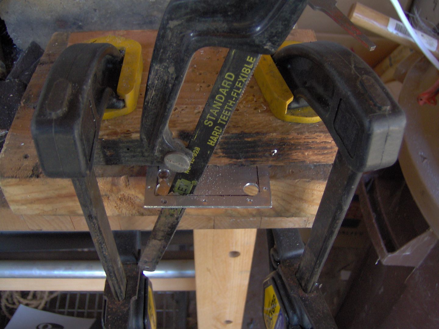
So let’s cut a panel for the voltage indicator side. Low and behold the Hack(saw)-A-Line jig, patent pending, ha, ha.
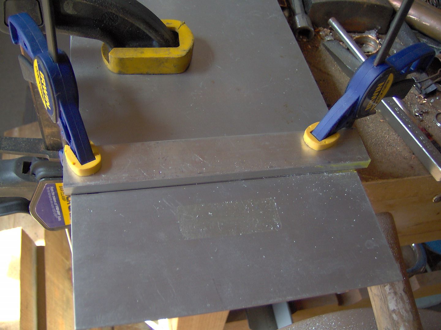
An ultrafine Sharpie and pocket rule is my friend.
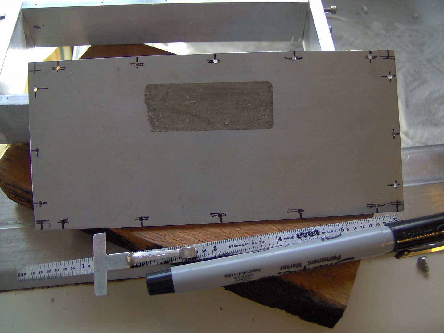
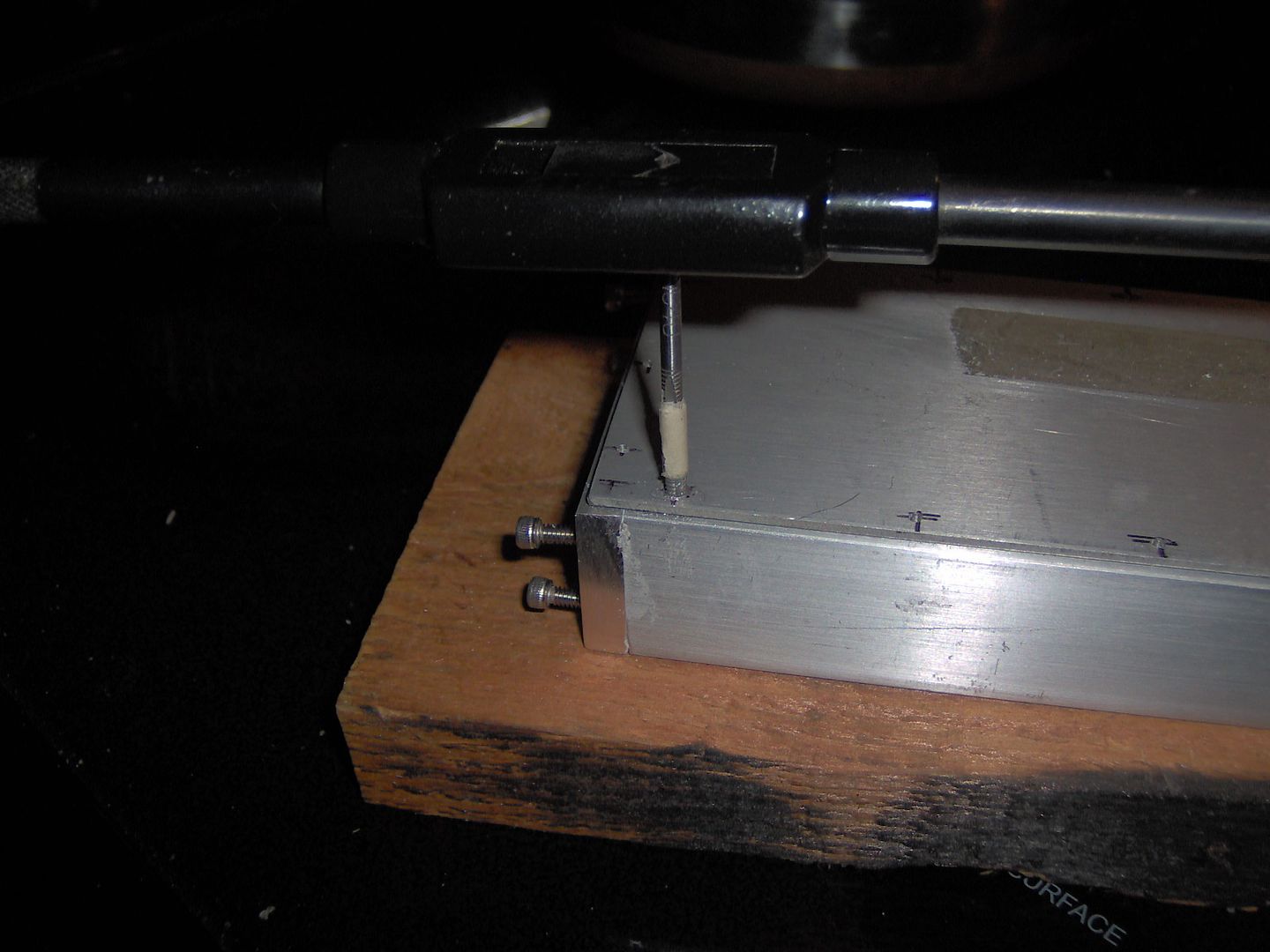
Drill, drill, and then drill some more. Tap, tap, tap and tap for the 4-40 screws. I tried the recommended drill size of a #43 (0.089”) but had a hard time getting the tap started. So went with a 3/32” (0.094”), it’s a little loose, but the screws seem to snug up just fine.
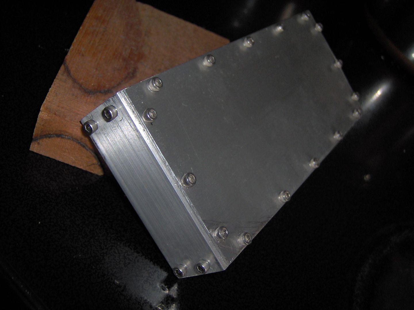
I can’t believe there isn’t a hole poking out the side or something here. Kinda looks more like an explosion proof enclosure as opposed to a solar flashlite. Broke a couple of 1/16” drill bits, but no tap yet, whew! I thinking I will change out the socket head screws on the side panel to button heads once the project is complete.
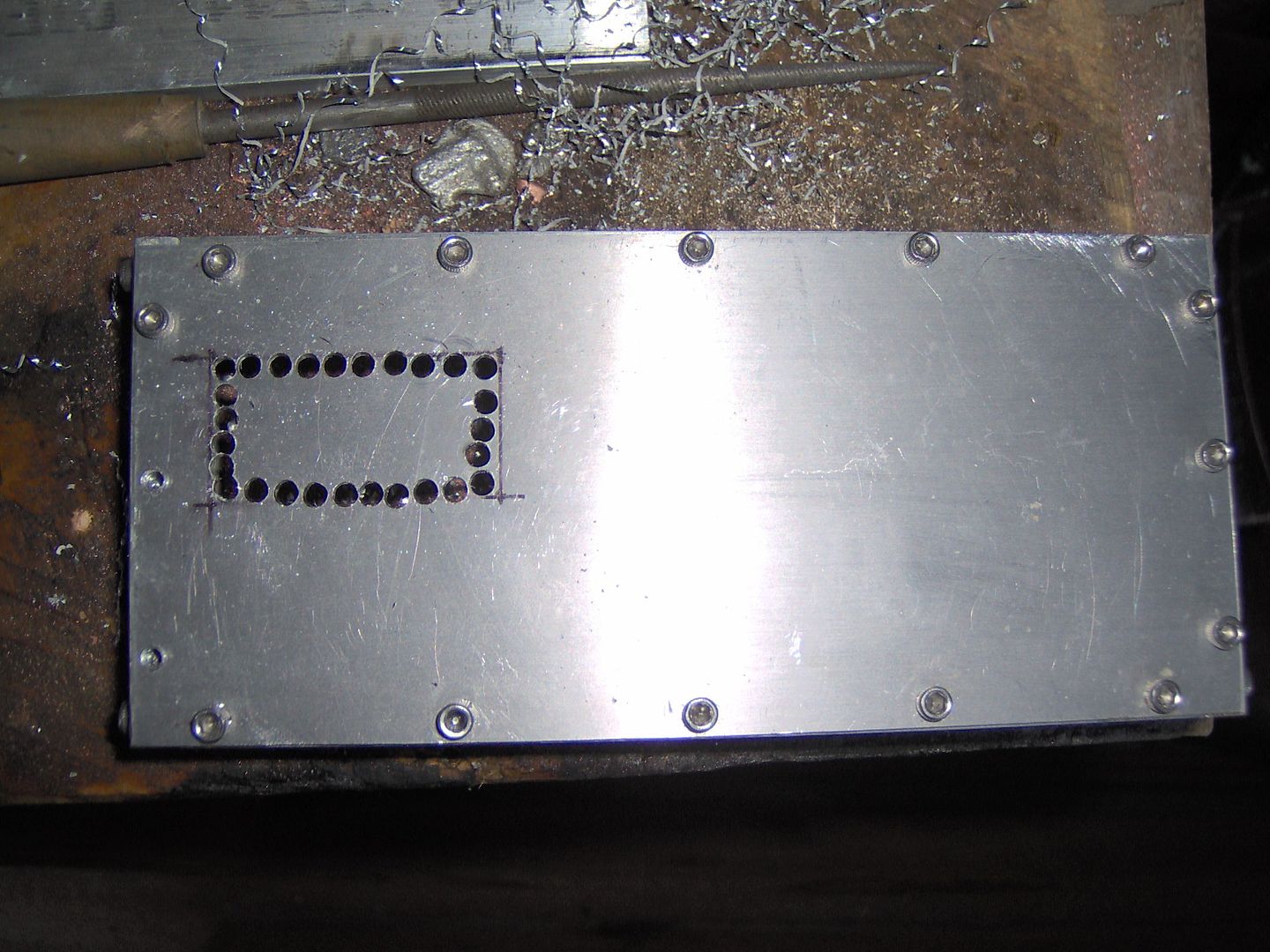
Time to make a window in the case, somehow I always leave myself plenty of filing to do afterwards. Lots of holes, and some nipping between them with some diagonal cutting pliers. The half round and round bastard files seemly in constant use on this build.
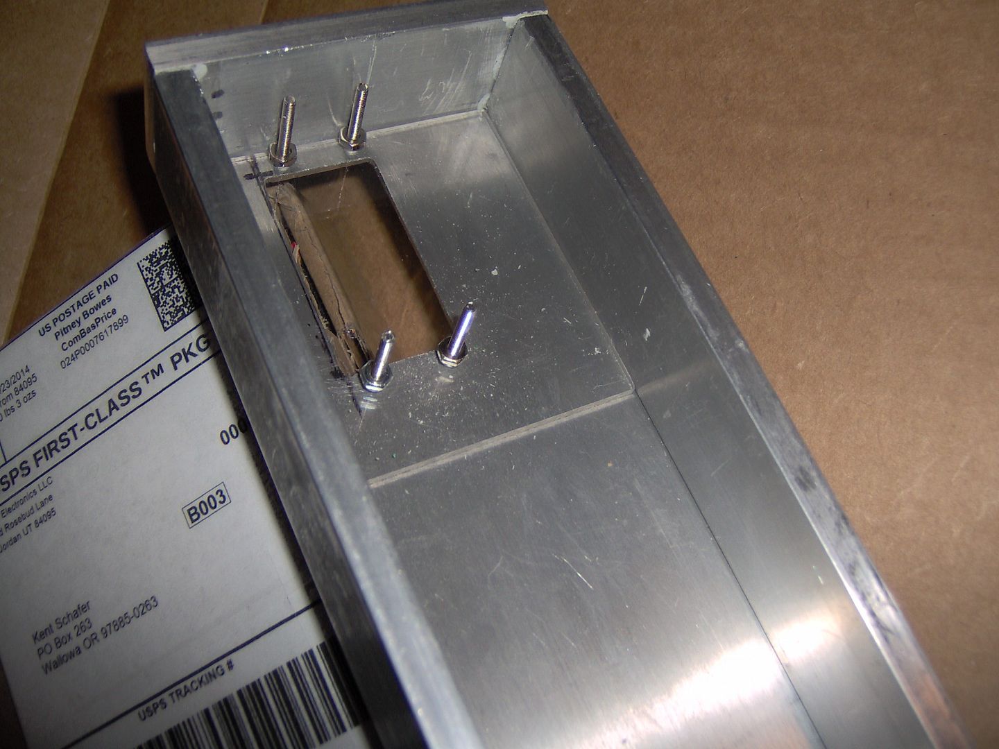
Using some 1/8” lexan sheet that I had on hand for the 7 segment window, then secured with some 2-56 screws. This also creates a standoff for the pcb board.
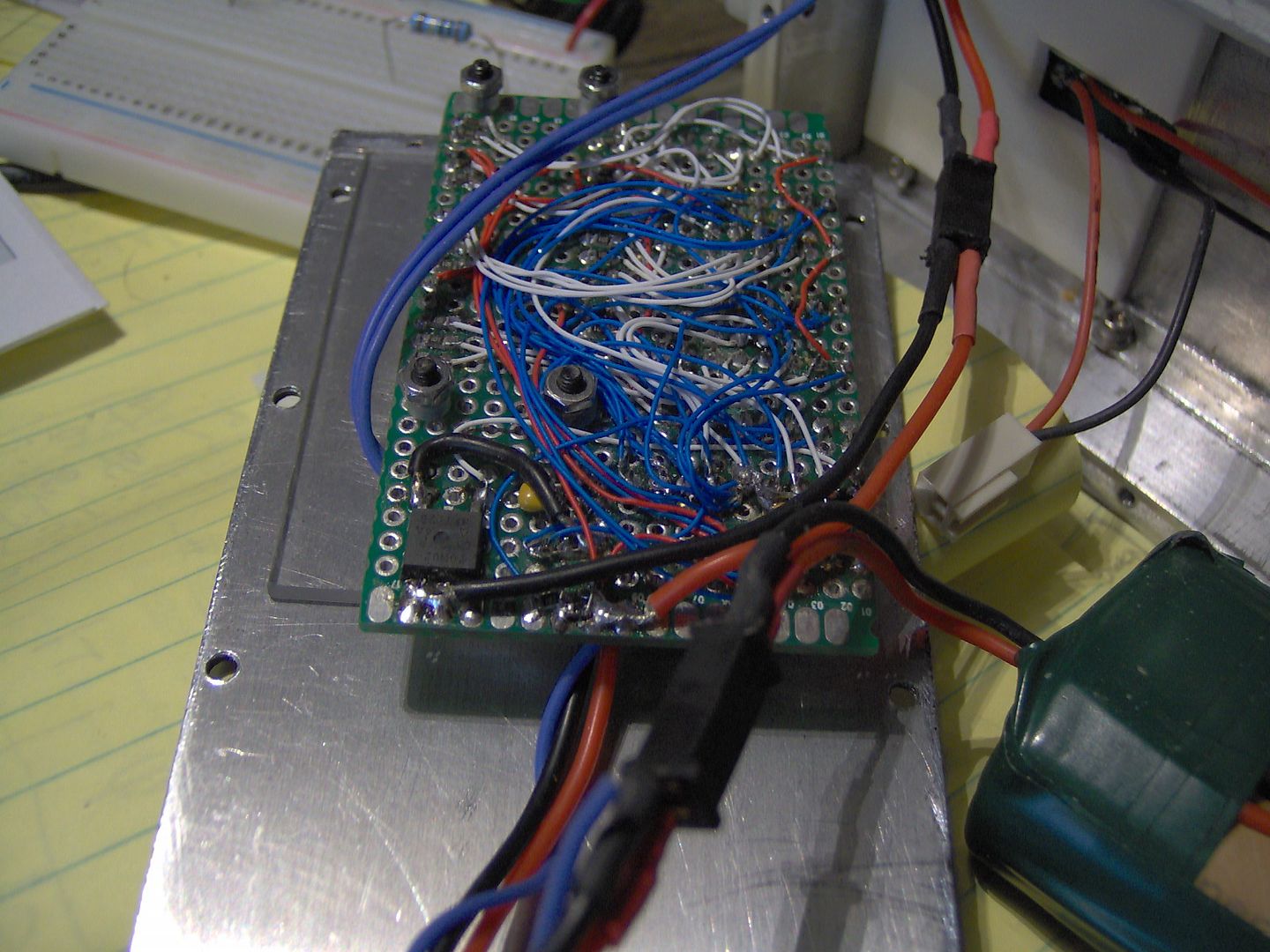
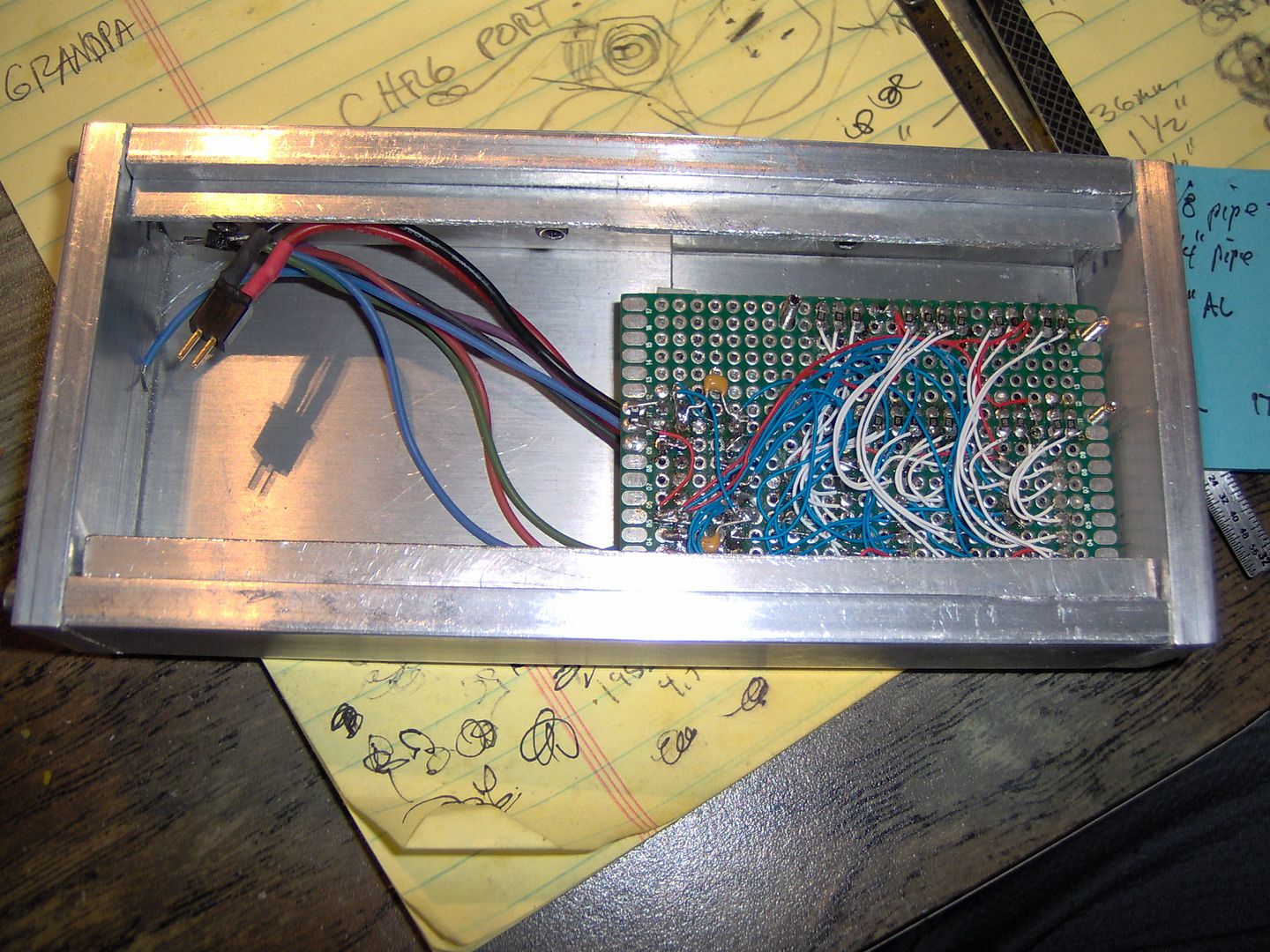
Mockup, with the pcb board and battery, everything is a snug fit so far, and looks like everything still works. Using point to point wiring with some 30 ga. Kynar (wire wrap) makes for a real nice birds nest. Didn’t I tell myself, that I wasn’t going to do this pt. to pt. stuff again?…oh well, rules are made to be broken I guess ![]() .
. 
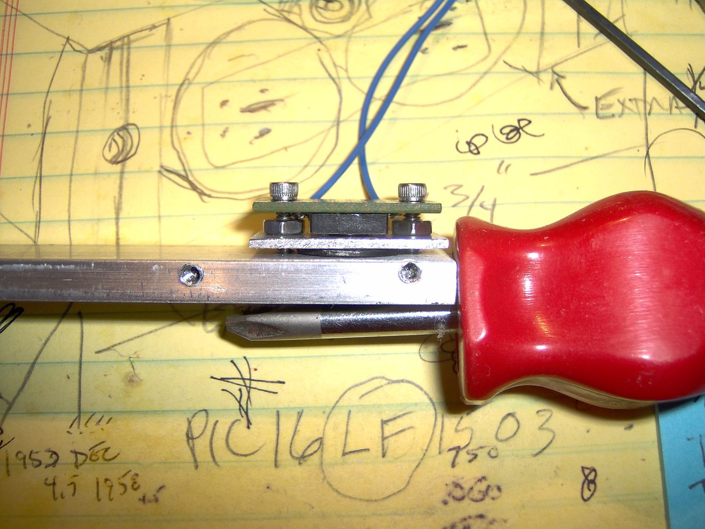
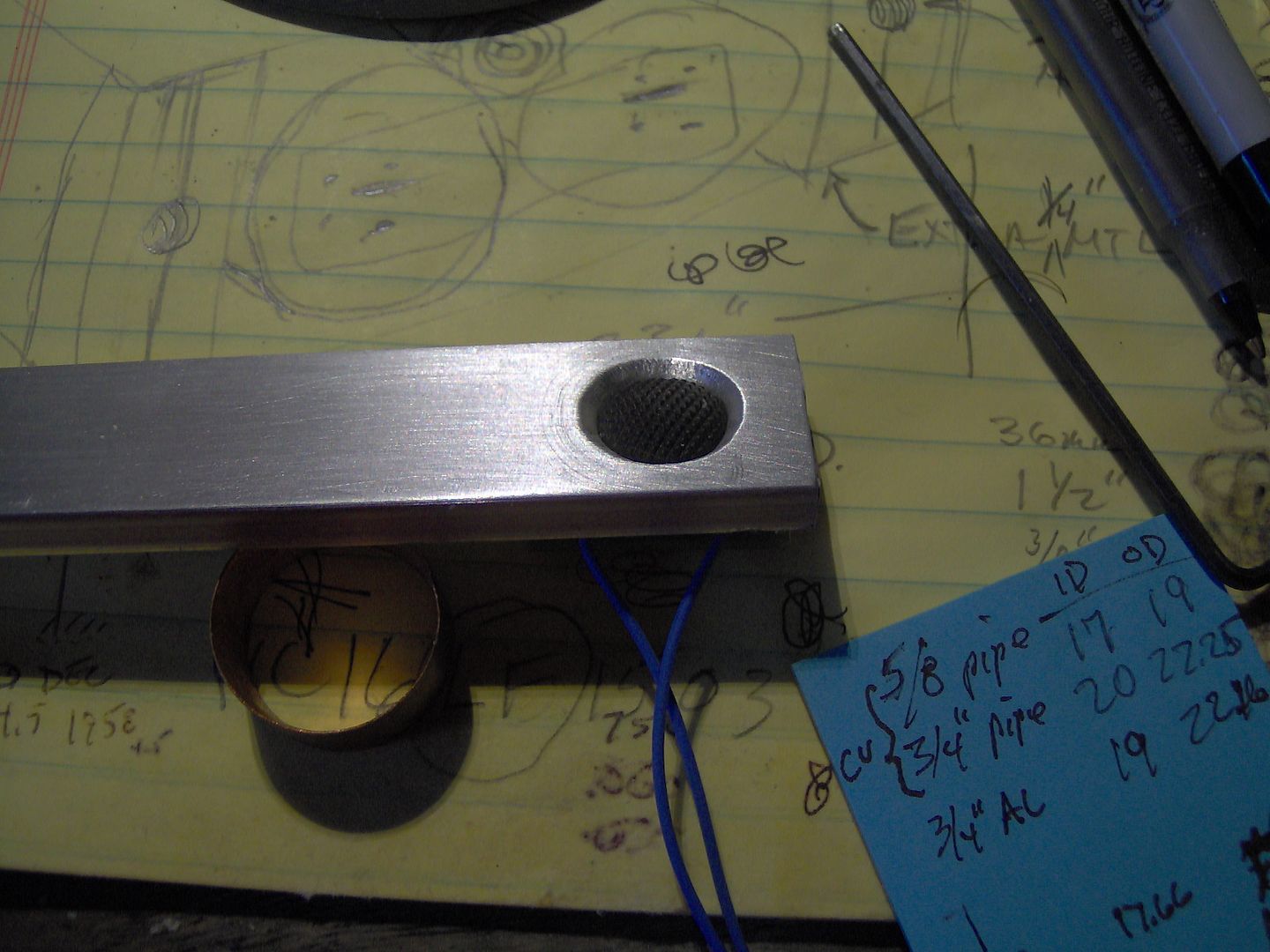
Time to start work on the pill. Added a couple of copper discs to fill in the recess of the C8 pill, where the star would normally be placed. This should get good heat transfer from the Noctigon mcpcb, thru to the aluminum frame. One thing I noticed was that when applying pressure with the thumb and forefinger to the pill, then moving it across the bastard file, made for a high in the middle (rocking horse) surface. By using a piece of 1/2” pipe to apply pressure in the middle, I was able to create a much flatter surface.
Got the momentary switch parts going. A stack up was created to keep the 14mm x 6mm switch boot in place with some aluminum plate and then the 12mm switch (robbed from a remote switch) is soldered onto a piece of proto board. I expect to glue a piece of nylon bushing to the push button, so as to make up for the slop created by the spacer plate. A jst plug was used for a quick disconnect from the main board.
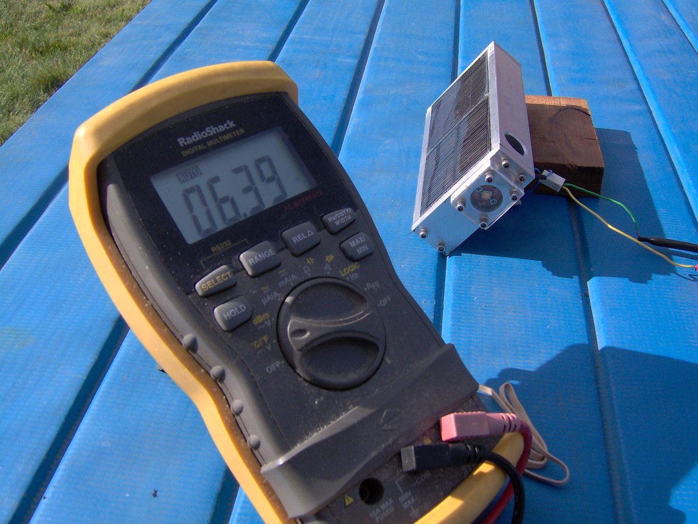
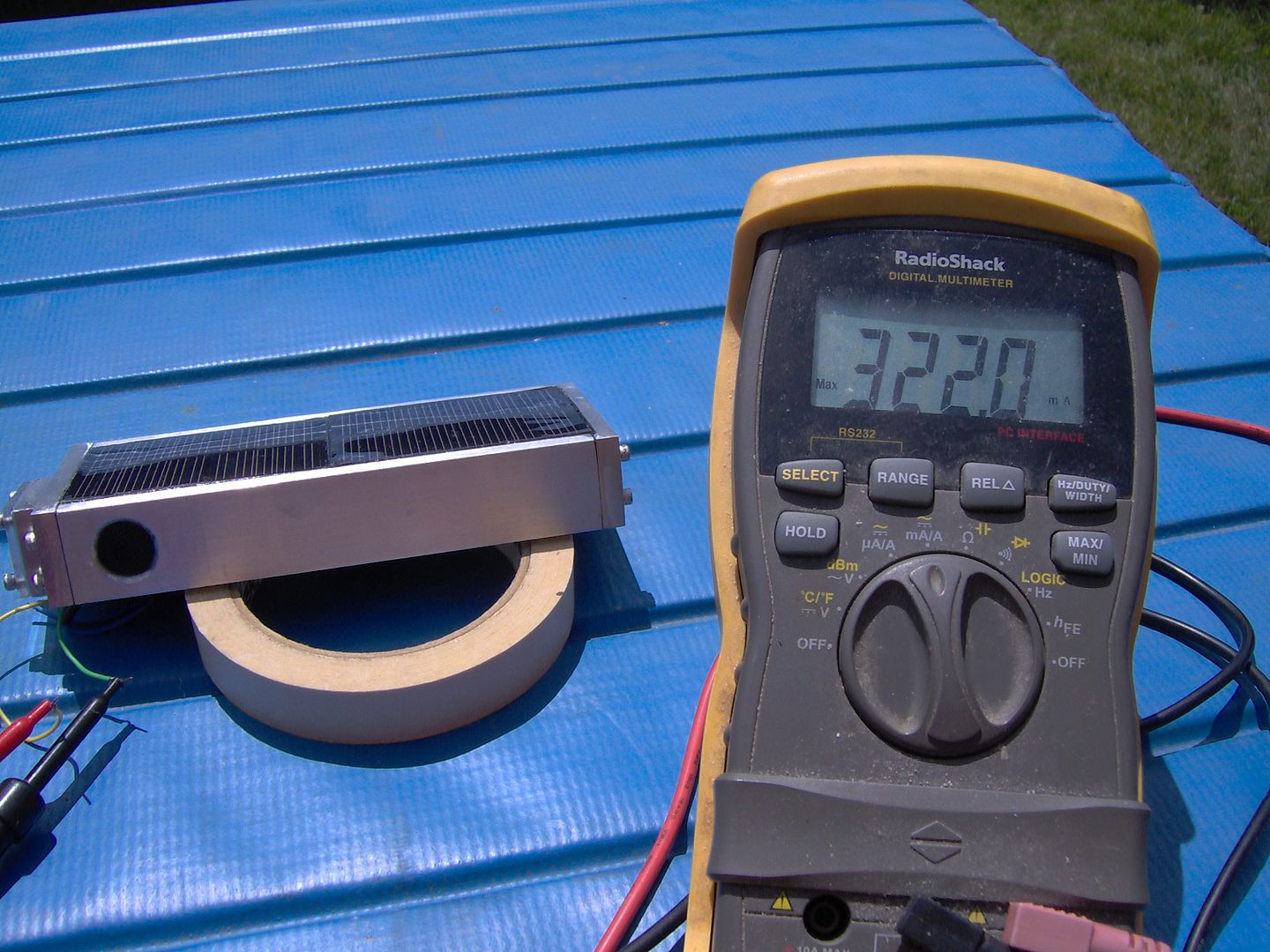
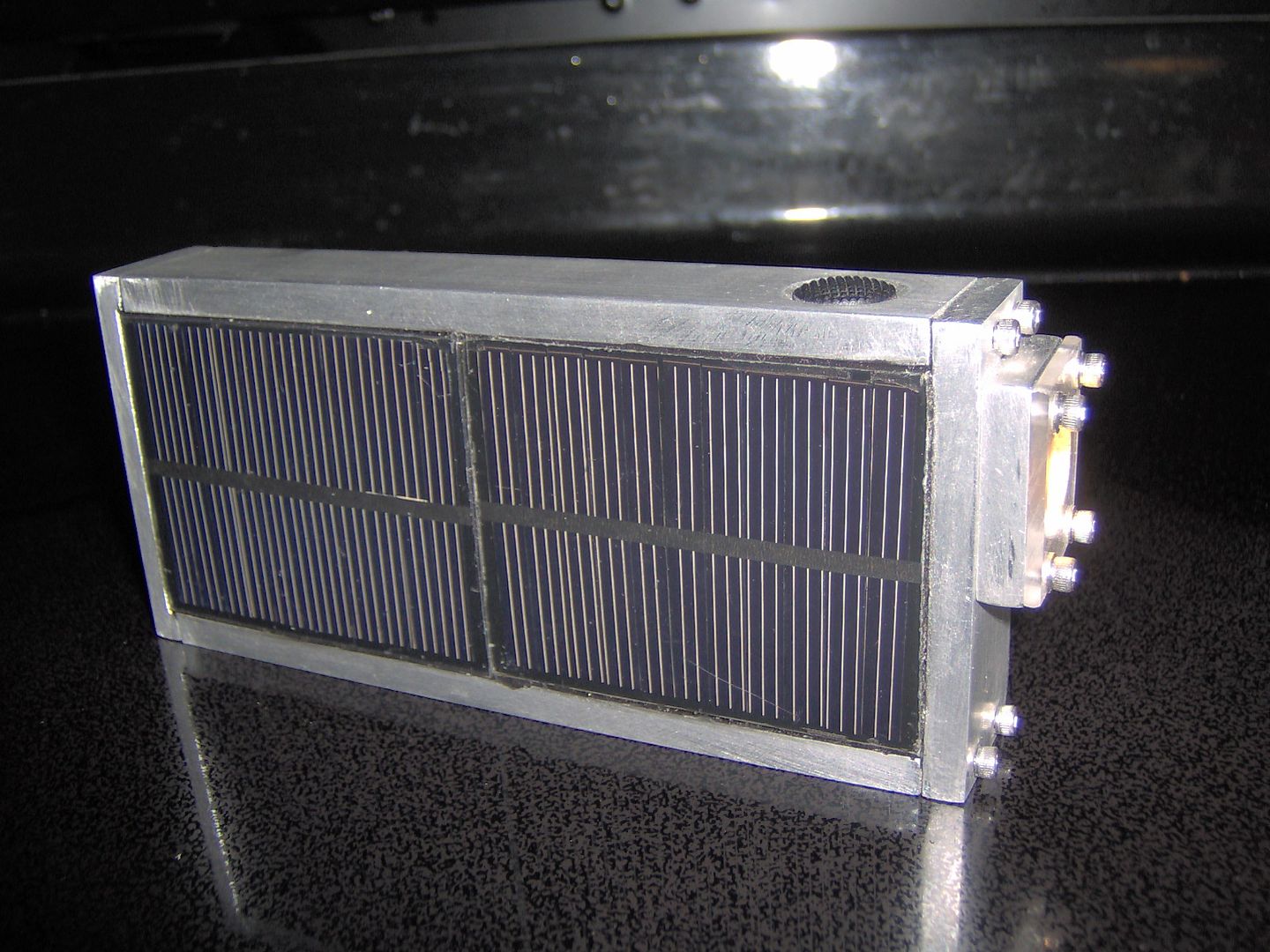
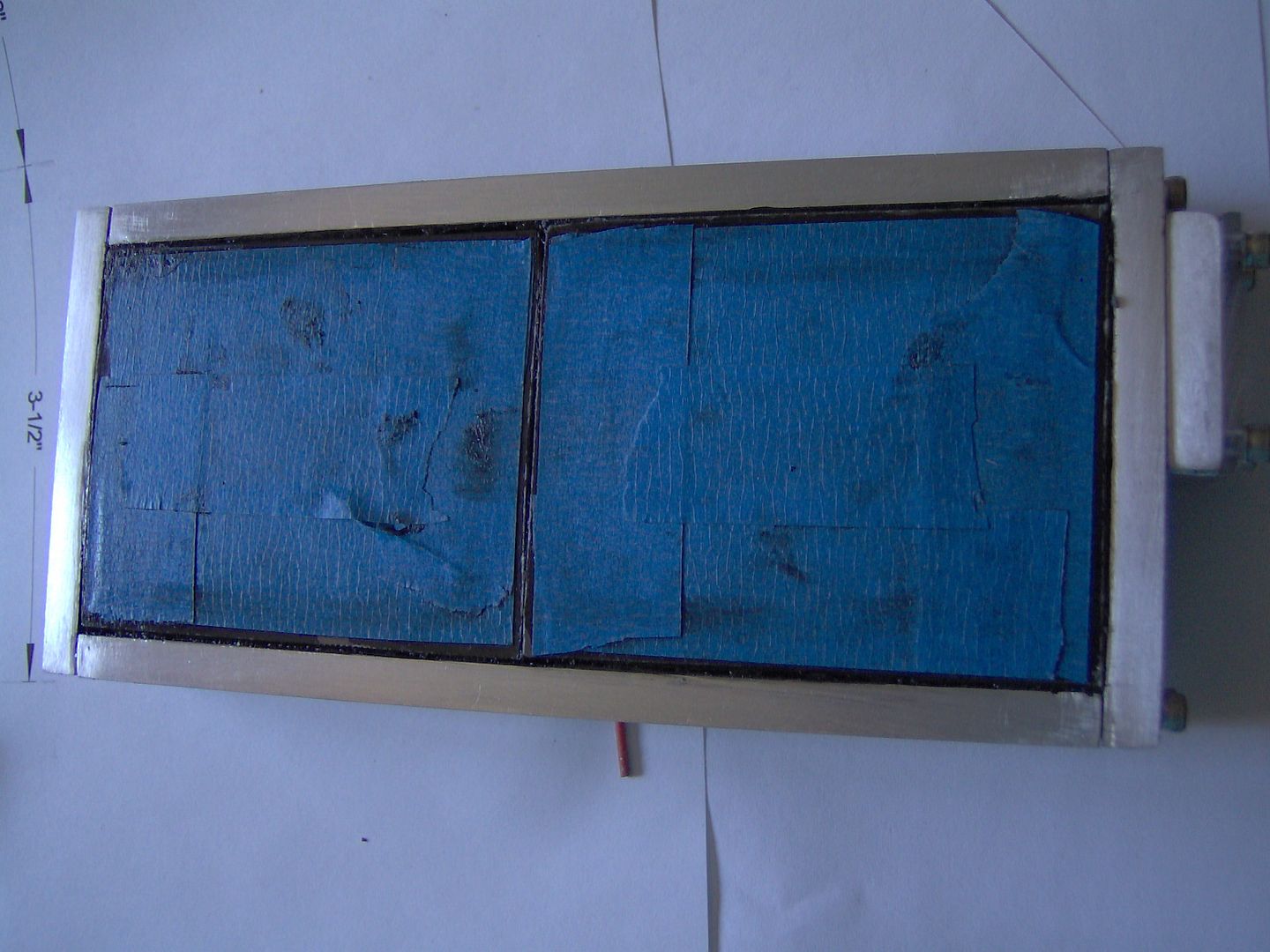
The solar pv panel side of the lite is going now. Cooked up some homemade AL 1/4” angle rails, then mounted them to the main frame with some more 4-40 screws. Also more .060” AL sheet laid in on top of the rails to create a back plate for the mini panels. A small bit of filing was required to fit the the panels length wise (EDIT: don’t do this…damages conductor leads). The panels will be silconed in when the lite becomes finished.
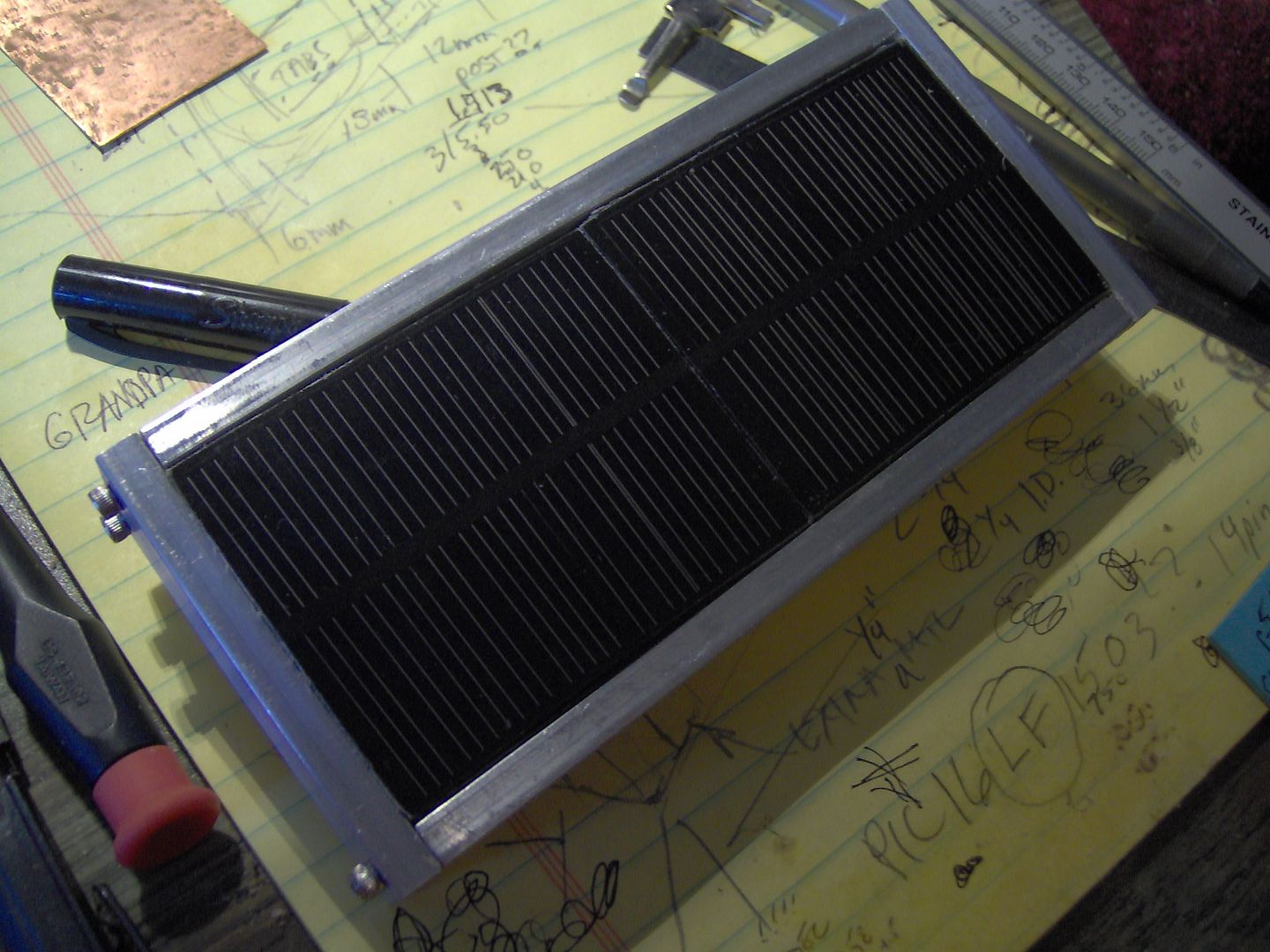
Here the panels are set in silicone, and ready to wire.
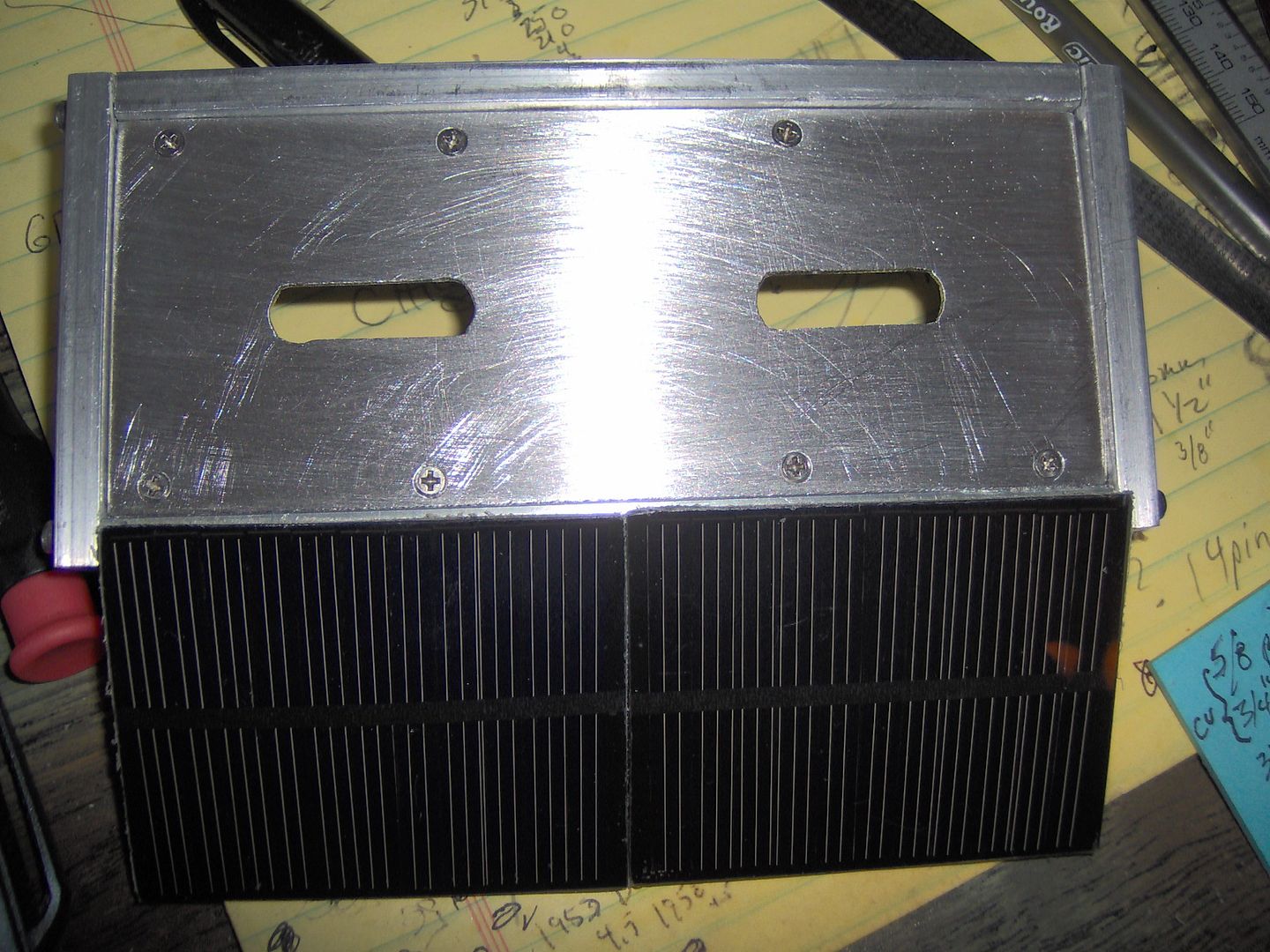
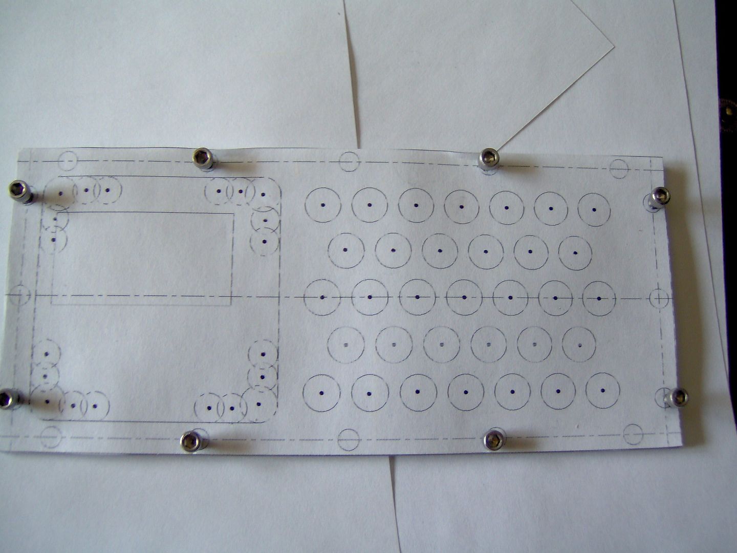
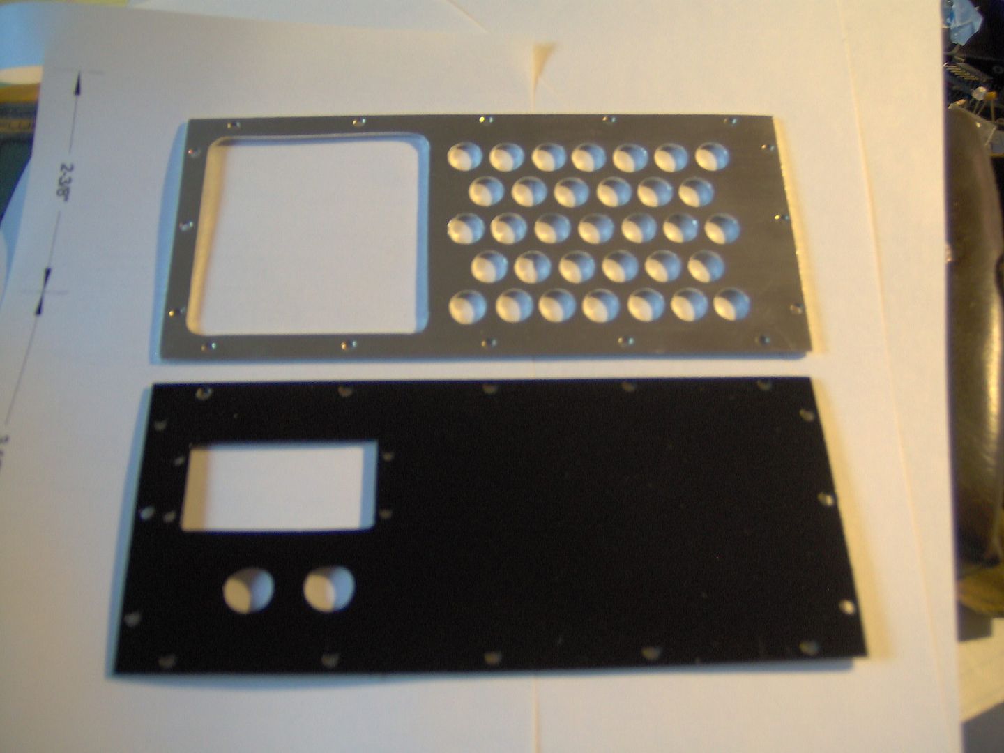
Things are looking a little plain on the 7 segment display side, so set about adding a decorative face plate. A CAD drawing was used, so I could try and keep the center punch inline, and overall layout uniform. The original faceplate made a good template for the cutout and attachment screw holes.
Cutting out the window for the inset display panel.
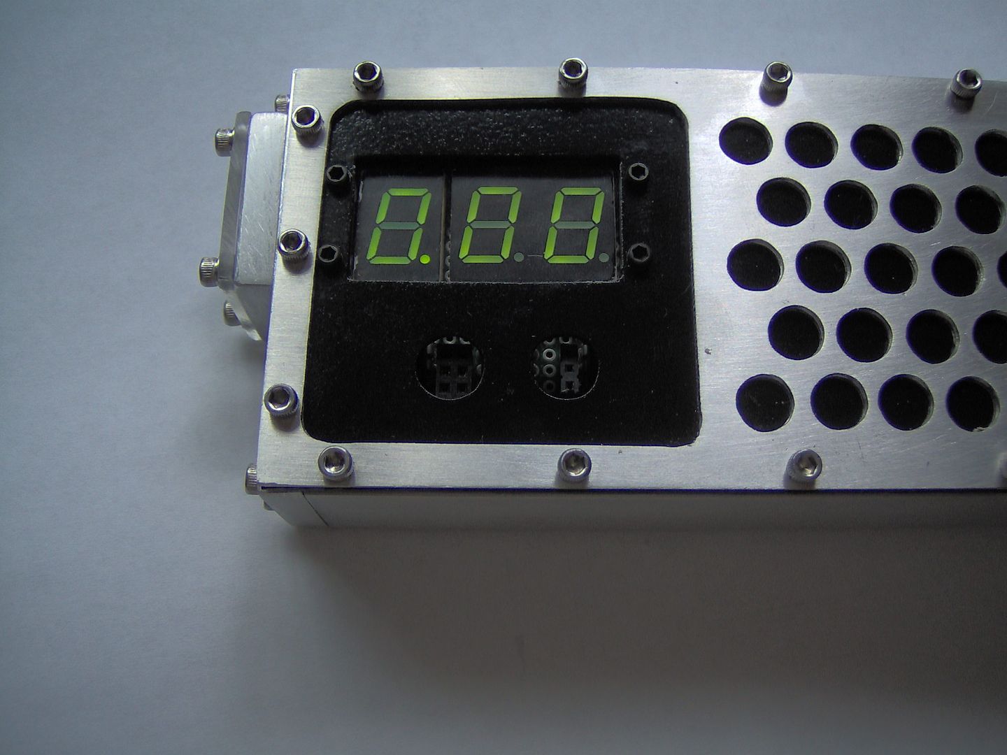
Finished decorative faceplate. Lets drill for the programming and UART ports, and paint the back faceplate black for contrast.
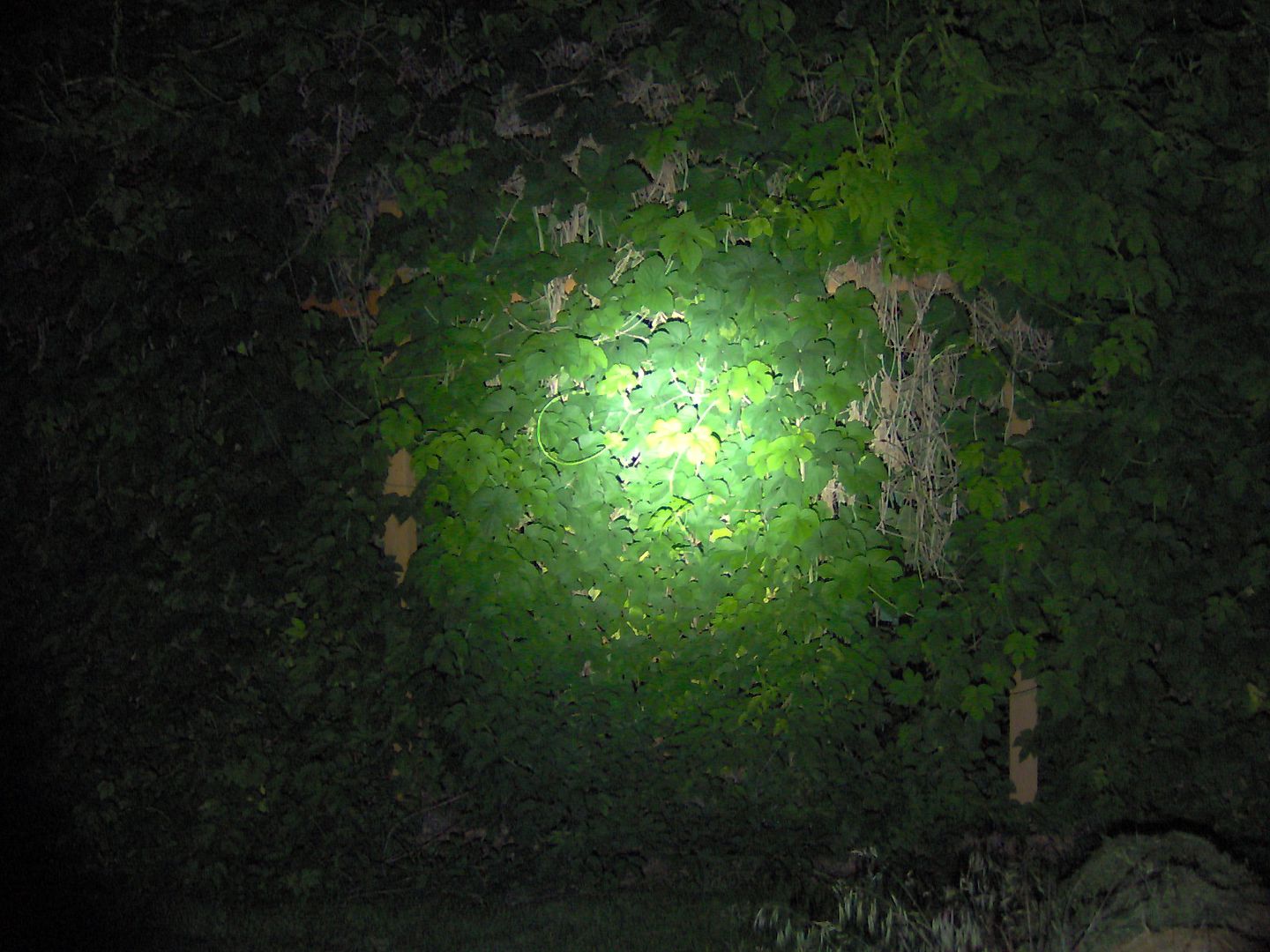
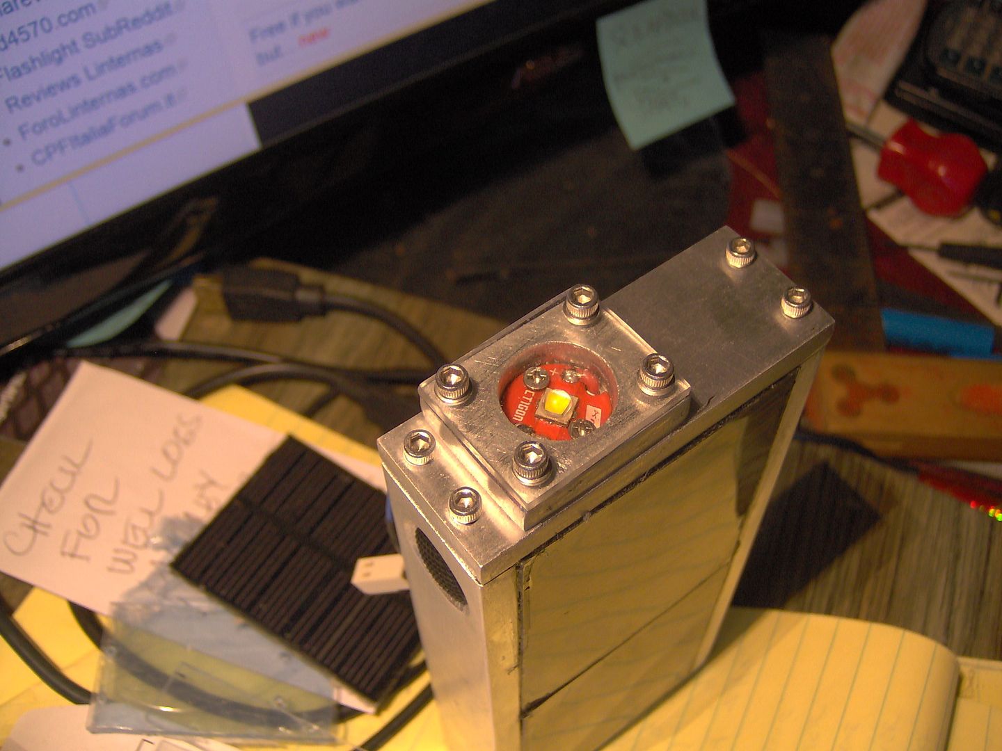
Big visions of doing the upside down C8 pill and a TIR, and it just didn’t happen (at least for now). So that and about 5 other iterations with a reflector and so on, still nothing. Finally, it is just screw the noctigon direct to the frame with a little Artic Silver Ceramique 2. Used a piece of the 1/4” x 1” AL frame material and a little Lexan for the cover. This accounts for the pure flood in the beam shots in post #2.
Here is the final trim for the Solar Rechargeable FlashLite. The blank grommets are covering the programming port on left and the UART port on the right.