This is the Tangsfire C8 I bought from Tmart two months ago, one of the most popular C8s among BLF members. Purchased at $13 with discount coupon during that time. I was working on other light and kinda busy so it sat in my shelf and never got my attention until last week. This is a very basic and simple mod for many members around here but I still thought I would share this. I open for any questions and suggestions about this light and mod.
Here-we-go!
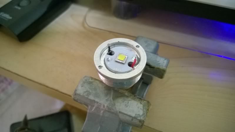
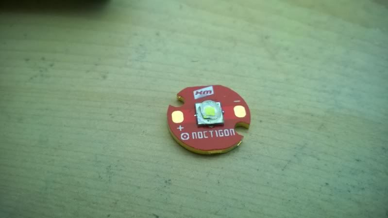
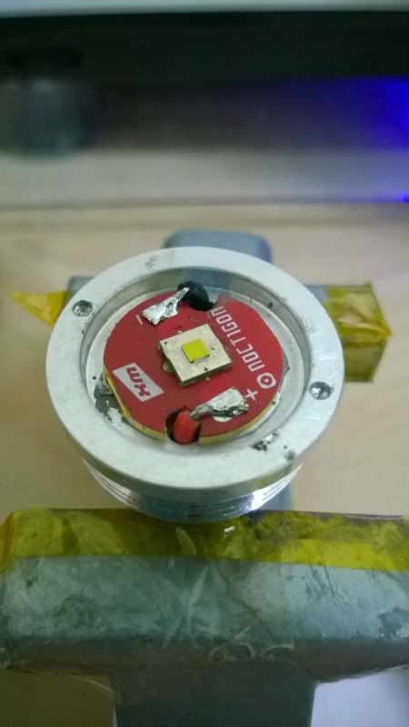
The stock emitter and star. They are going to be removed and I would reflow the stock XM-L2 (unknown bin) onto a 16mm Noctigon board.
I wanted to try Vinh’s method to dedome the LED, but failed! I had no idea how hot the LED should get before it’s time to lift off the dome.
Nevermind, let the gasoline method to do the job.
AS5 + a bit of Fujik under the star.
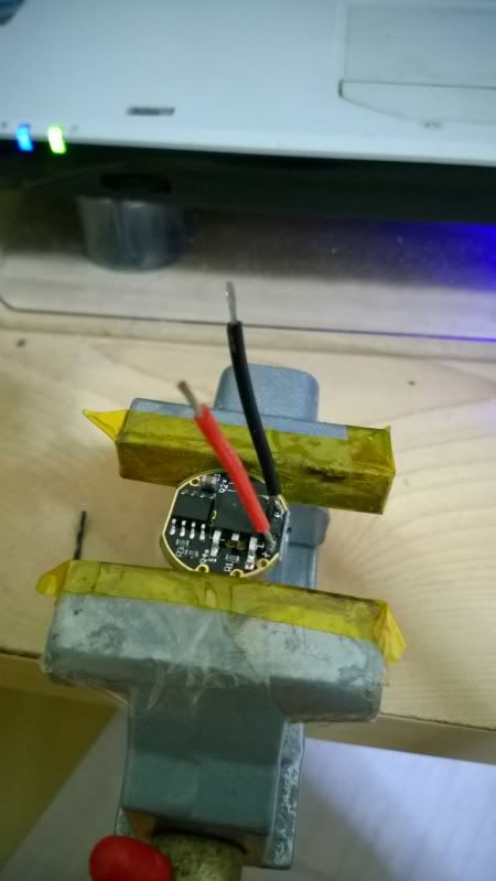
22AWG silicon wires soldered on the East-092 driver for allowing high current drain.
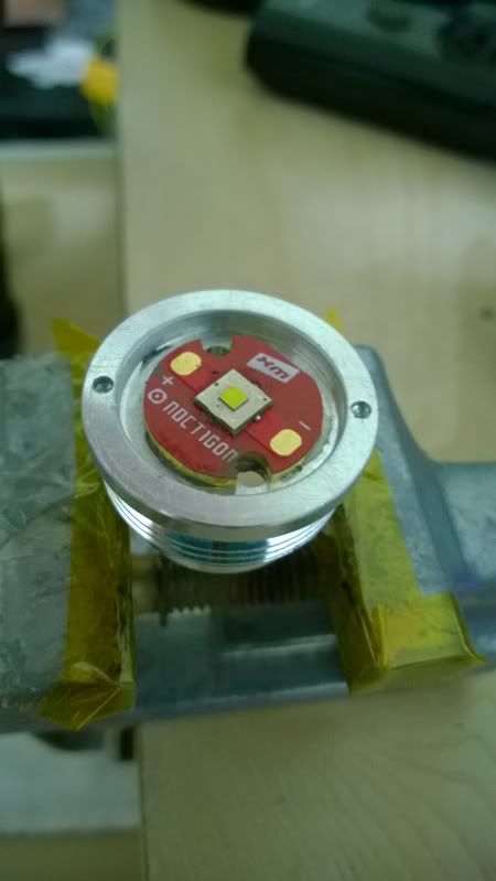
Now solder everything together.
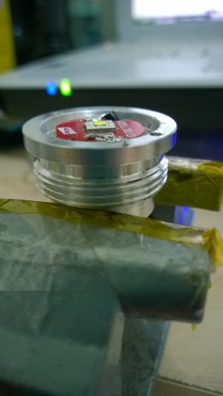
And I tried my best to make the solder joint flat as much as possible so that it won’t make contact with the aluminium reflector and able to sit deeper into the reflector to have better focus. Of course insulation is still needed for safety consideration.
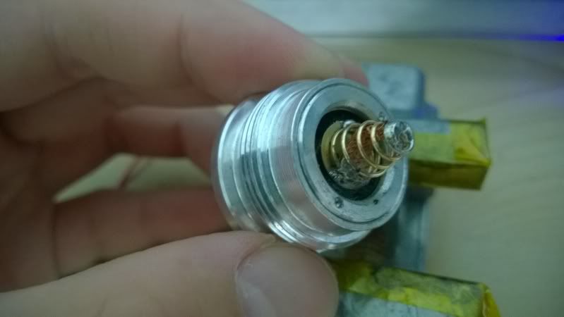
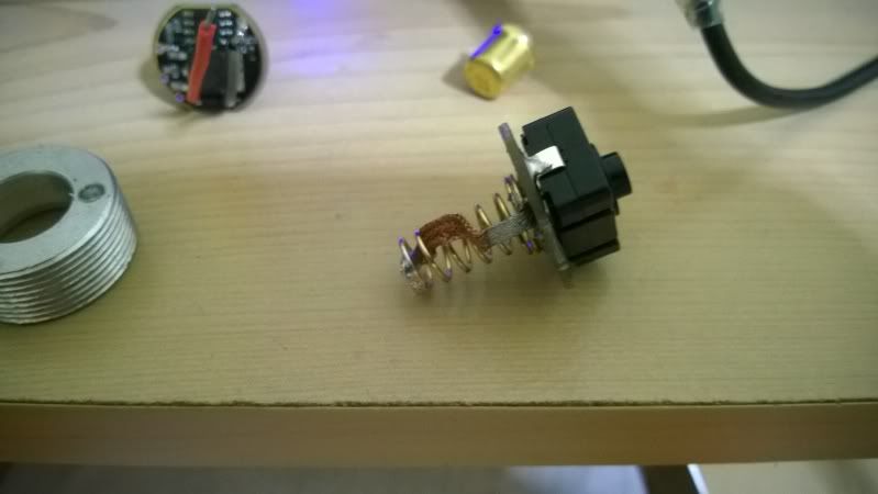
Copper-braiding (has this became a word already? Lol) the spring on the driver as well as the switch. You can refer to Old Lumens tutorial videos on how to do this, his explanations are much more detailed and clear.
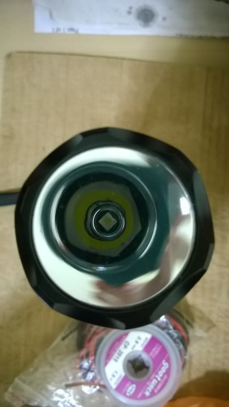
Put everything together and done! This thing pulls about 4.8A on high with Samsung INR 20R @4.19V.
Nice…most basic yet most POWERFUL type mod there is
With that copper noctigon pulling the heat from the emitter the body should get plenty warm w/o over heating the emitter…what kind of modes does your east-092 run?
Thanks WarHawk-AVG. Indeed this is one of the most effective mods we have known so far.
Yes, on high mode for more than 5 minutes the head gets pretty hot and uncomfortable to hold. The East-092 is pretty much a typical budget light’s driver: 5 modes, Hi-Med-Lo-Disco-Disco, and very obvious PWM frequency in Med and Lo mode. Anyway I don’t really mind it because I simply want the high output and fun out of this light. I already have other lights with good modes so no worries.
not much else you can do apart from just removing the driver and make it true direct drive, the build can easily handle that and if it is the high mode you are interested in anyway.... :-)
scooby214,
You are welcome and hopefully this can help you a bit.
djozz,
Yeah a true direct drive is simply wiring the battery to the LED, that’s it! Although the lower modes have horrible PWM frequency but they still serve their purpose at least, so I would just leave it like this at the moment. In stock form the wires are not even 22AWG, maybe something like 26AWG or so, not to mention without copper-braiding on any spring at all.
Looks good. I believe that Vf goes up some when xml2 emitters are put on copper. I think Match's testing indicated that, but I think he had some reservations about his Vf measurements. I'm too lazy to look up Djoss's testing results right now. A higher Vf will reduce current because the cell has less juice to deliver at the higher voltage.
EDIT: Here is a link or Post 51 from Djozz's xml2 on copper crash testing. I don't know how the Vf compares to aluminum though.
Could it be that if a bond wire is broken, it would change the Vf? Vf is dependant on the LEDs resistance, and 3 bond wires paralleled should have less resisntance than 2 bond wires paralleled. Perhaps this might even be the case if the protection diode’s bond wire is cut?
Anyways, nice mod. I need to find my copper braid!
I too try to flatten the wire ends before tacking ’em down and soldering on the star. No matter how pure my intentions, it always looks like crap! nice work there _
jerryg, I usually leave it in the gasoline for quite a long time, from 12 hours to 24 hours. I have done this gasoline dedome method for many times already but I thought I wanted to try Vinh’s method as it looks a lot faster.
ImA4Wheelr, some people said it may be the dedomed emitter causing the higher Vf, and some said it is due to the copper star, maybe both have combined effect. Until somebody carry out experiment on these.
Sorry for the pic quality, but what do you mean by “a gap under the thermal pad”?
BShanahan14rulz, but I never heard about it is due to the broken bond wires… by the way, if the bond wires are broken it is basically a trash, it won’t even lit at all.
Sorry for the slow reply. Have not been on much this weekend and there are a ton of threads active right now. Gap - I appears in the picture that there is a lack of solder between the emitter and the Noctigon for the center pad. It could just be a optical illusion. Hard to tell by just the picture.
I put in an INR 20R battery leaving it on high for more than 5 minutes, the head got very hot but the tint of the LED doesn’t change at all. I did this for several times and the results were same. So I think it is fine, the heat dissipation is good.