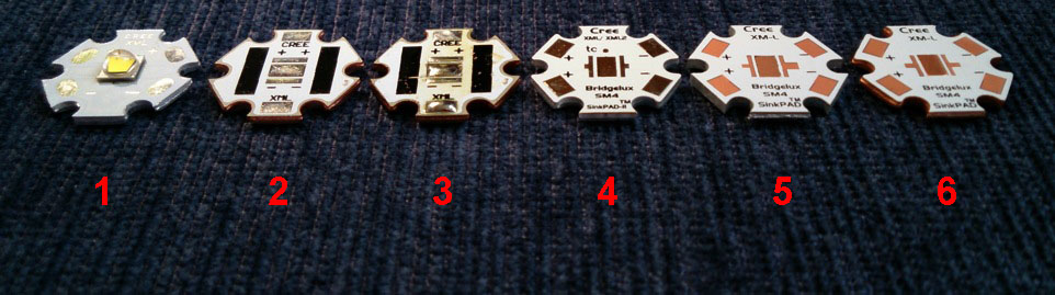
1) common aluminium board, in fact the board the XM-L2 3B led was bought on, from Fasttech.
2) copper board with traditional dielectric layer under the central heatsink-pad, from Fasttech
3) same type of board as 2), but with the dielectric layer removed under the central pad, the gap filled with solder
4) aluminium Sinkpad, version1 (with the shallow gap on the underside of the board where the central pad was punched up)
5) aluminium Sinkpad, version2 (flat on the bottom, the edges of the board a bit rounded, reveiling that it is a punched-out board )
6) copper Sinkpad, version1 (with the shallow gap on the underside of the board where the central pad was punched up)
EDIT: correction: rollinstone157 pointed out correctly that I swapped the two alu Sinkpads in the above picture.
In another thread BLF member rollinstone157 offered me some Sinkpad samples he had sitting around doing nothing. It later appeared that he could not find them anymore, so he was so kind to ask Sinkpad for some new samples especially for me to test. They agreed but asked for some quite extensive testing in return, especially to compare them to the various copper boards around that -unlike the Sinkpads (and Noctigons and IS boards)- have a dielectric layer under the heatsink-pad. I first wanted to do a limited test but was eventually happy to do the whole lot because I was curious about it, and so are some BLF-members I understand.
Relic38 did some very precise comparisons already (more professionally than me) between the different direct-bond copper boards around here and here. This test I did now is different types of Sinkpads versus non-direct bond boards, using the same led reflowed six times successively on the different boards and testing the performance.

I have recently bought a new lineair power supply. The display on the power supply shows a current reading that I really wanted to use for tests, because it just is easier, it saves me putting an extra amp-meter in the circuit. So a thing to do before testing these boards was checking the current reading of my power supply against my (mid-quality Amprobe) multimeter. For who wants to see the numbers:
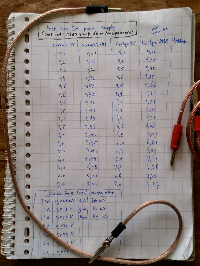
The power supply and DMM agreed on the current within 0.1A, even closer at higher currents, I was happy enough with that. I also made some new test leads out of thick speaker wire, the bottom shows a voltage drop measurement of the black one (70cm). These long leads are suitable for use with the power supply, but I will make shorter ones for doing current measurents on flashlights with the DMM.
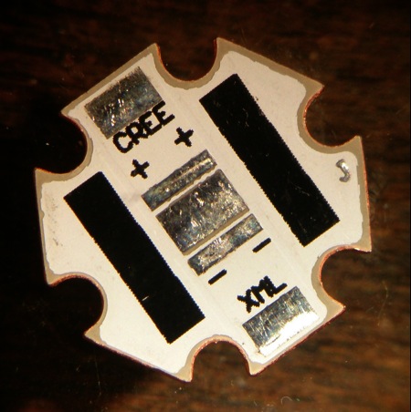
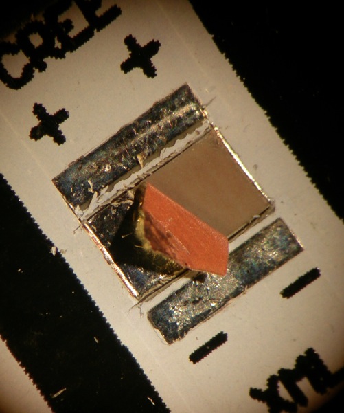
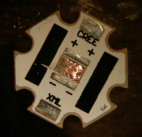
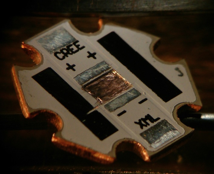
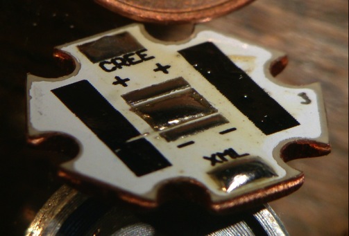
One of the -to be tested- boards was a cheap copper board with dielectric layer (I bought mine from Fasttech), with the layer removed, exposing the copper core of the board, and then the gap filled with solder. I used a scalpel to cut out the center pad, with a forceps removed the solder pad, then scraped the dielectric layer away with a small screwdriver, and on the reflow block filled the gap with solder. The work was tedious enough for me to happily next time pay a bit more and buy a proper direct-bond copper board, but in the true BLF-spirit this is the way to go of course :-) . Some pictures of that:
Everything is ready for the comparison. The 'reflow station' that I use for more than a year now is a 12V solder iron on a small power supply converted with an aluminium block, it has no temperature control other than that I know that at 9V reflow does not work because the solder will not melt, and at 10.7 V reflows go fast and smooth. I guess that the temperature of the led will not get excessively high in this this set-up.
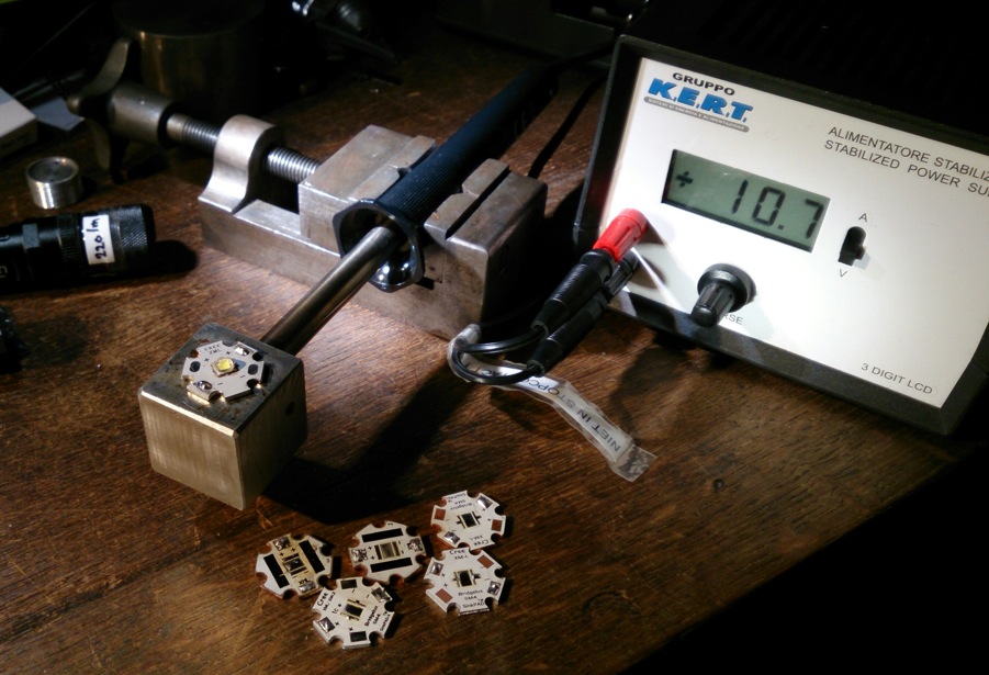
The test set-up is my usual one, but with new power supply :-) , led-board screwed down on chunk of aluminium, tiny bit of Arctic Silver5 in between, board is directly connected to the power supply, current reading comes from power supply, voltage is measured at the end of short and thick wires soldered on the led-board. On top of the led is a C8-reflector facing the ceiling. Light bounced from the ceiling is measured with a (cheap but proven reliable) lux-meter.
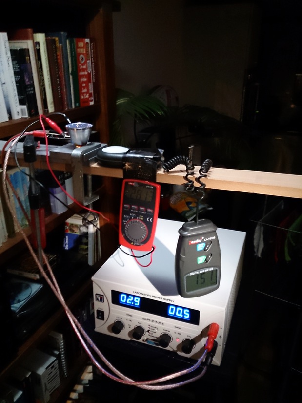
The luxmeter was taped in position and between different measurements just the led-board was removed from the set-up so that the position of the board next to the luxmeter was exactly the same in all measurements. Normally I calculate the lumen-numbers from the lux-numbers using this-set-up-specific conversion-factor 1.22 , but the C8-reflector blocks a bit of the ceiling bounced light, so it is not accurate in this case. So I only give the lux-numbers in the graph, for comparison between the boards. (I do suspect from this test though that my led was a lower bin than T6...)
I started the test with the led on the original aluminium board. I first turned on the current to 5A for a moment to 'burn in' the led a bit, probably did not do a lot, but I thought that it was fair that also the first test was done with a 'used' led. After each measurement series I removed the led from the board and reflowed it onto the next board. All those reflows did not leave the led-dome undamaged, it got a bit 'bobbly' over time and at the end of the copper Sinkpad test, at 7A, something on the led-dome burned and smoked.
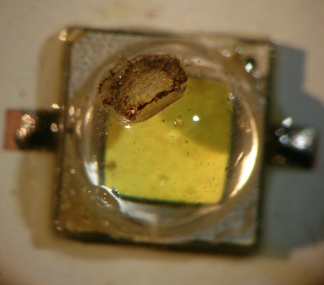
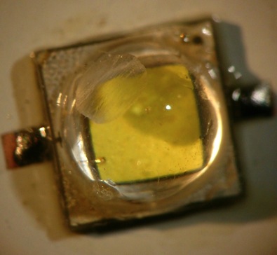
I had to cut a bit of the dome off with a scalpel, and measured the led again on the same board: I got the same output, apparently damaged domes do not really influence output (but will affect the beam a bit of course). I ended the test-series with reflowing the led on the original aluminium board to see how much the performance of the led had suffered from the test-series (lux2 and V2 in the picture below, and measurement2 in the graphs). Here's the numbers that I gathered:
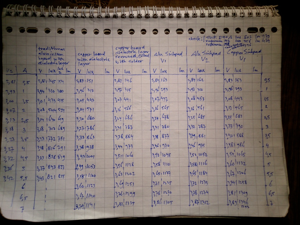
I made an output graph, and a voltage graph:
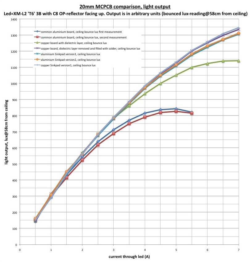

I always have doubts if my improvised set-up is good enough to do such measurements, so I was again surprised to see in the produced graphs that the measurements are not all over the place, and make very much sense :-)
I am also glad to see that after all the abuse the led reflowed on the original board shows a very comparable performance to the first measurements on that same board. It tells me that the measurements in between can be reasonably compared to each other, that I am not looking at a slowly dying led.
I think the results speak for themselves, but to mention some finds that I think are interesting:
-the cheapy alu board that the led came on performes quite well up to 4A, the output curve compares well to match's finds., exept that I find lower voltages. I can not compare these voltages with my own measurements of the XM-L2 I did last year because I used the power supply voltage then, which is higher than the voltage that is actually over the led (even measuring over the led wires as opposed to the actual solder pads of the led gives slightly different values, as Relic38 found).
-the cheap copper board with dielectric layer performs much better than I thought!
-that same cheap board with the dielectric layer removed and a thick layer of solder under the thermal pad performs as well as a copper Sinkpad! And even with a bit lower Vf, making it a bit more efficient. This I find interesting: perhaps because of just a bit worse thermal path it warms up a bit more than a copper Sinkpad, this lowers the Vf but does not really reduce output: the thermal management of the Sinkpad may work a bit too well in this test (no worries: in an actual flashlight there is more than enough compensation for that ;-) )
-the aluminium Sinkpads perform slightly worse than the copper one, but in real life it is the same, version 1 or 2 does not matter.
I hope you liked these tests. I keep to my belief that every measurement error under 5% is nothing to worry about ;-) . But I am always open to questions and to suggestions of how to do better testing within my humble possibilities (I am working on a integrating sphere right now, not for more accuracy but because it makes measuring a bit easier, and stops the neighbours from wondering what that lunatic is doing all the time pointing idiotic bright flashlights at the ceiling).
 . Perhaps the dielectric layer in the copper board has a lower thermal resistance as the dielectric layer in the aluminium board? I scraped that layer in the copper board away: it was not exactly a thin layer, much thicker than I expected actually.