I was not going to post anything till the end of the contest... Well, you had to know that would not last! I just figure there's a month gone already and not too many have started their builds, so here's a look at what the third place prize will be. It will either make you want to win third place, or it will make you want to run and hide, for fear you actually might get it as a prize.
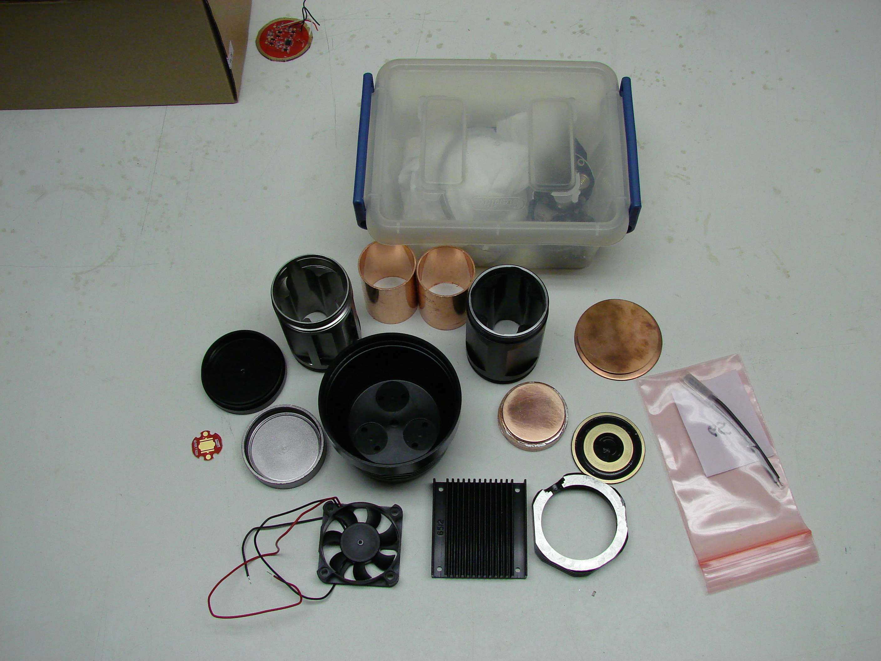
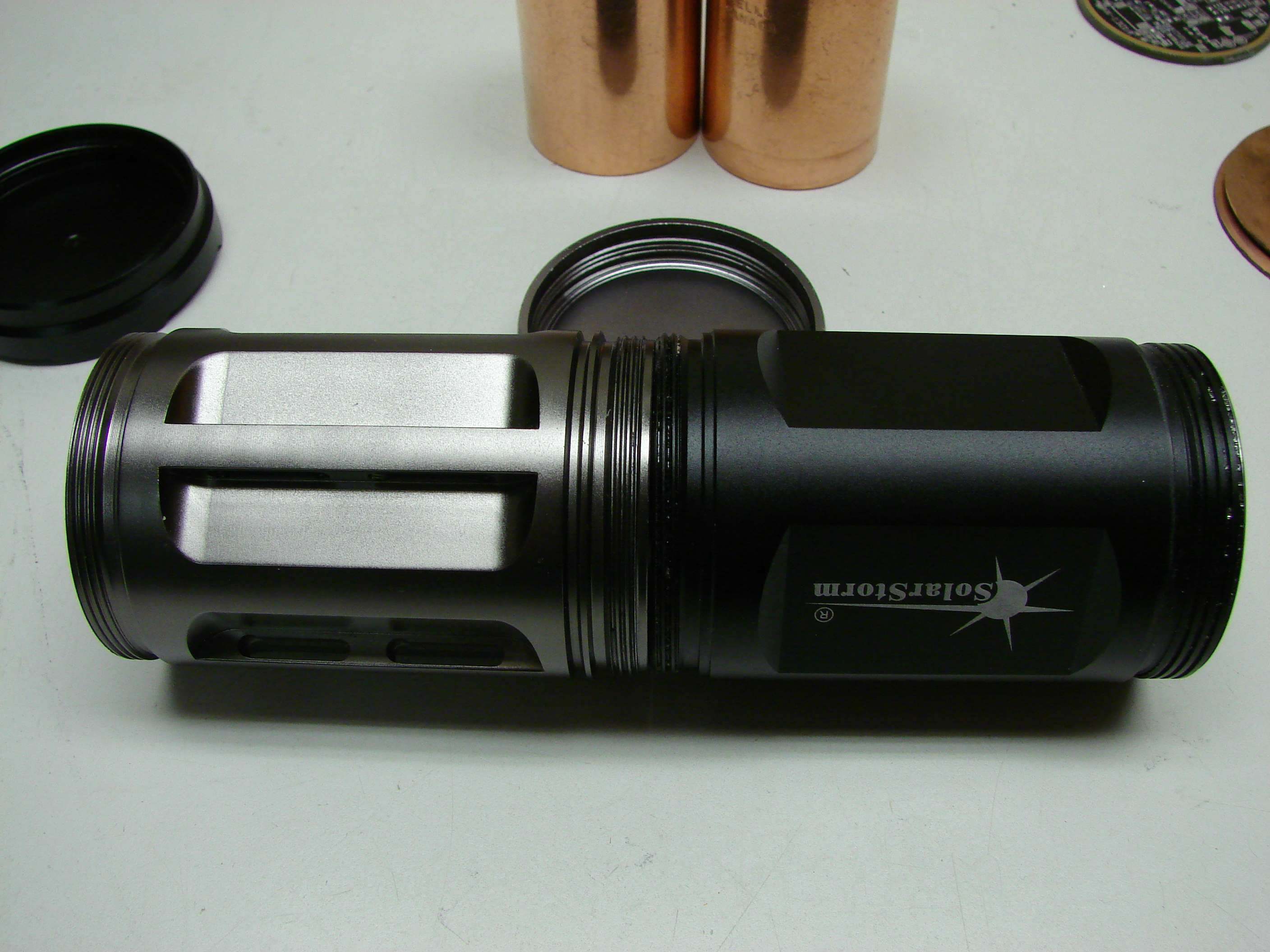
This is what I started out with and as things progressed, the components also changed to suite the needs. This is a Solarstorm SP-03. I am going to put 3xMT-G2 leds in it. I am going to use 8x18650 batteries in 2S/4P configuration. It will be fan cooled. It will not look anything like the stock light... I sure hope it works.
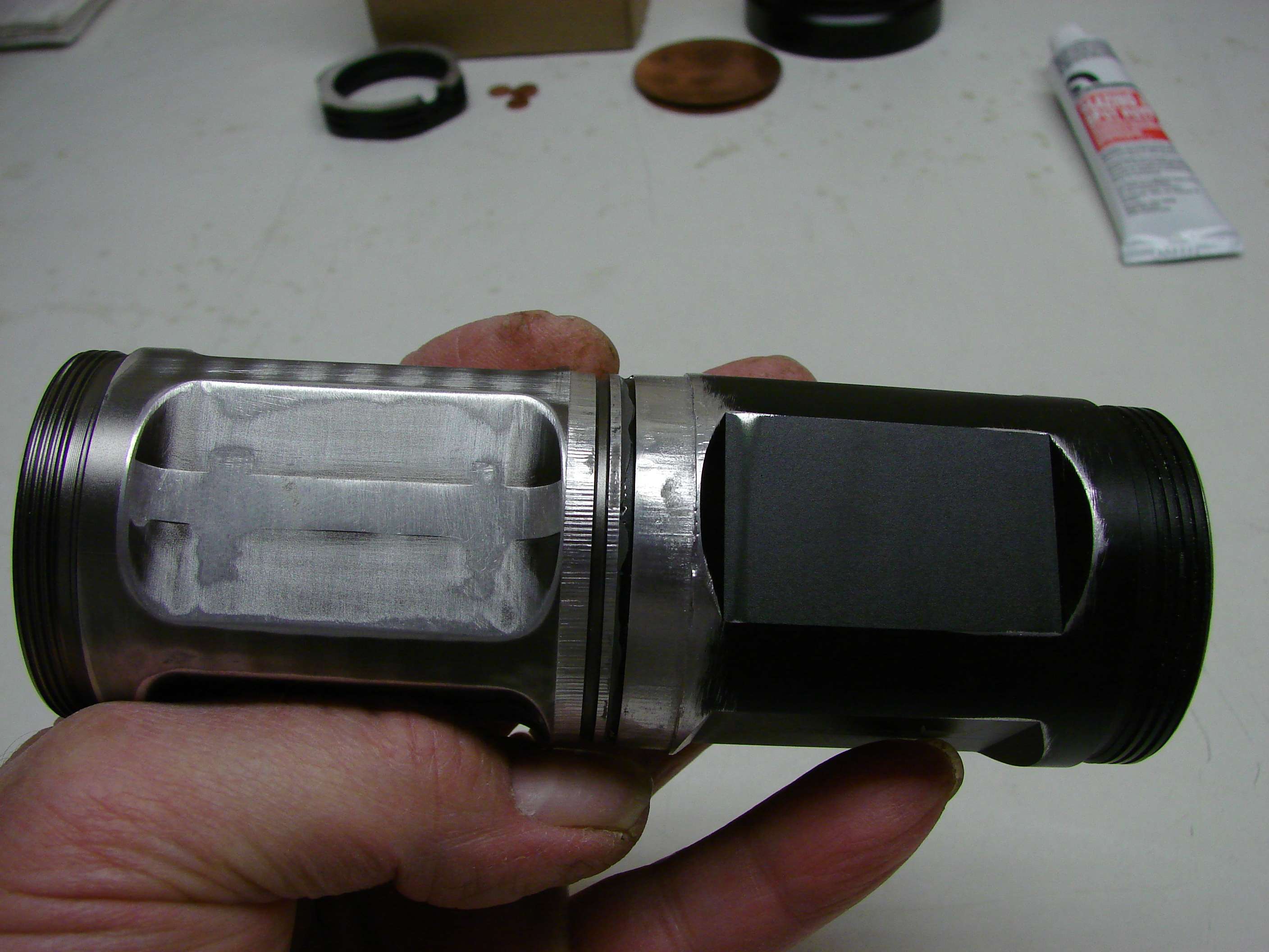
I put this photo in, because I did not take any of when I cut the head apart. I used a hacksaw to cut the head in two, right where the switch was. I am going to extend the head, to have room for the heat sink, fan and driver.
This is the copper heat sink that will fit under the stock led shelf.
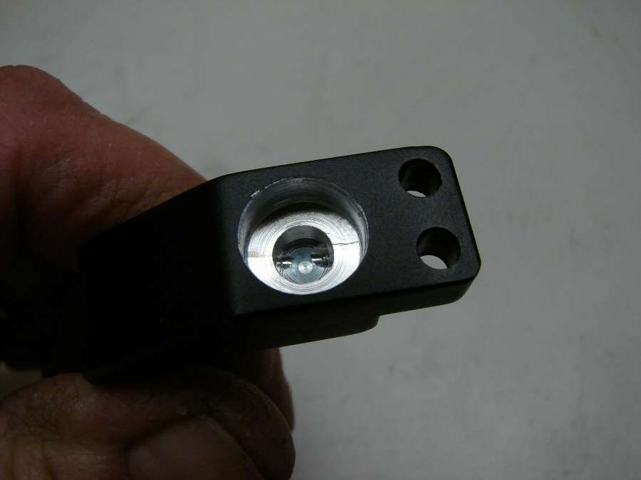
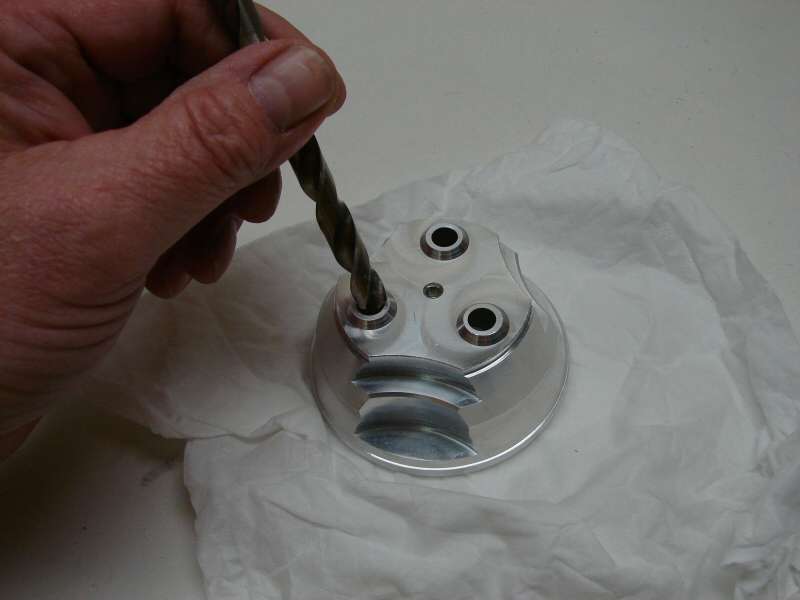
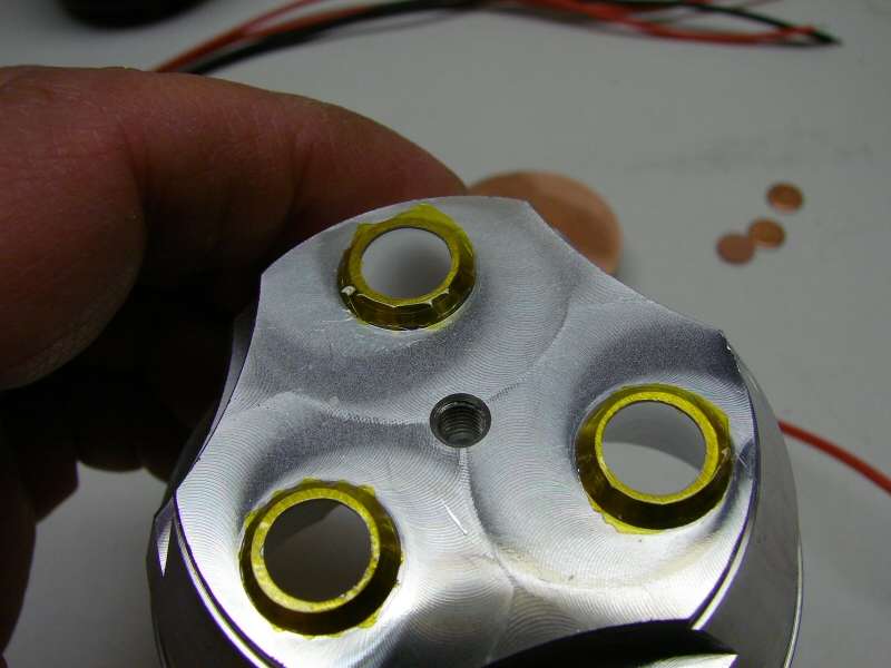
I did not like the dimples in the led pockets, so I drilled them out.

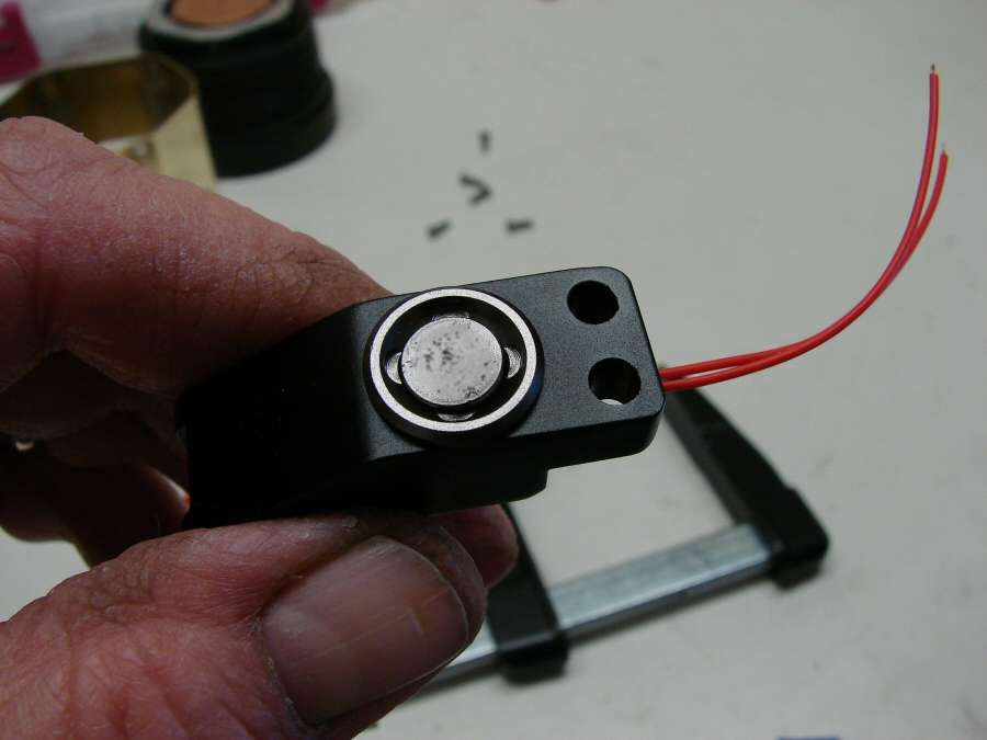
and replaced them with copper discs.
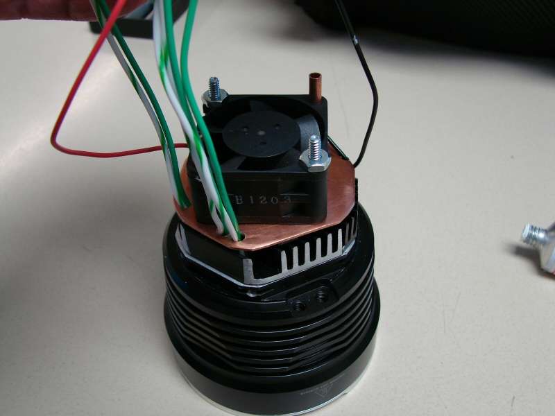
I got a finned aluminum heat sink and a fan. The fan here is not the one I ended up with. This one was 50x50x10 and the one I ended up with is 40x40x20. There was not enough foom for the 50mm fan, but the 40mm actually produced more CFM.
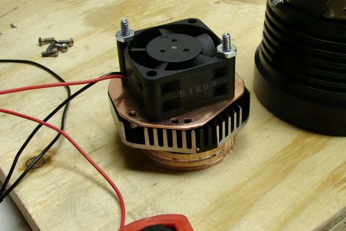
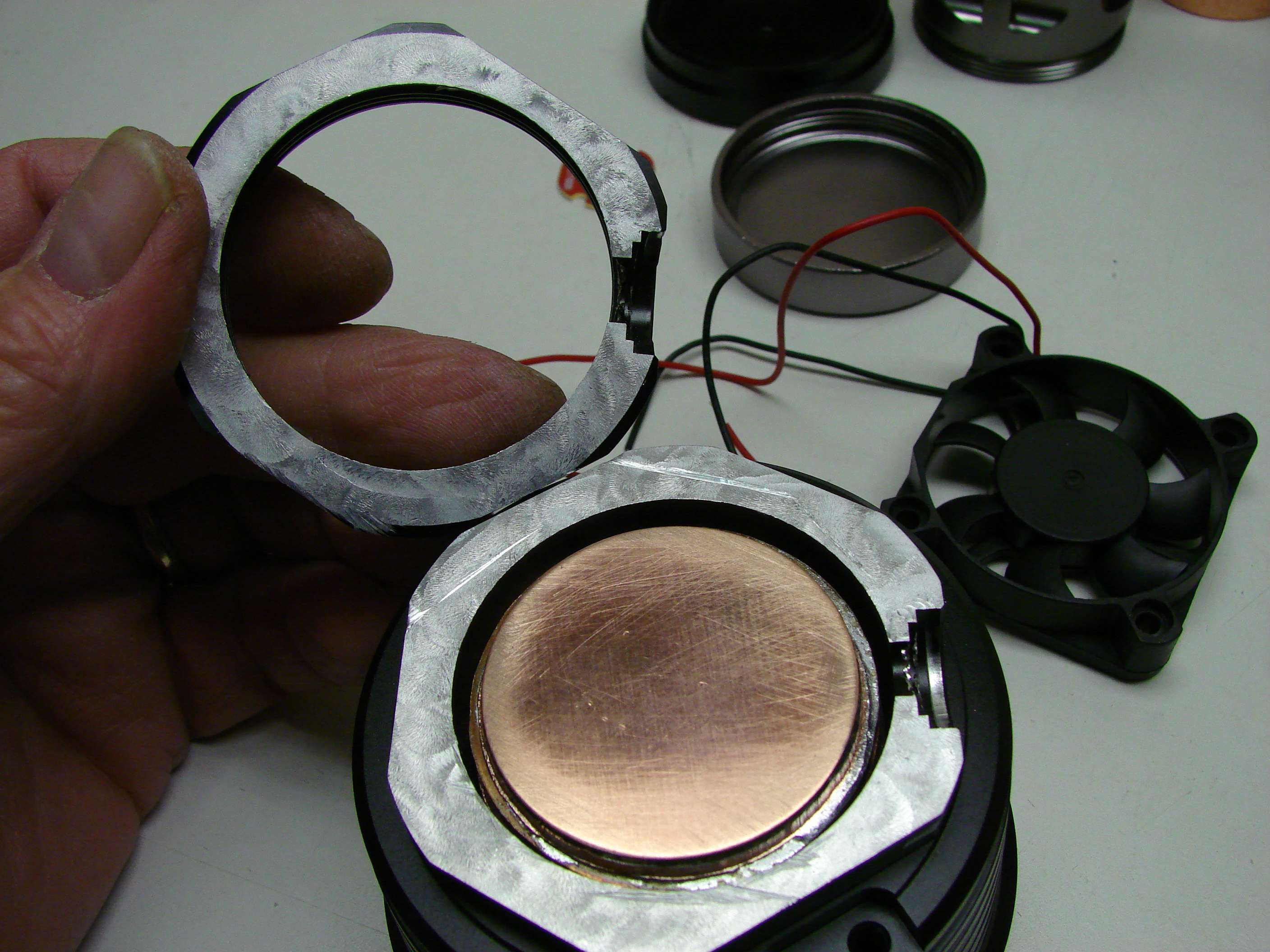
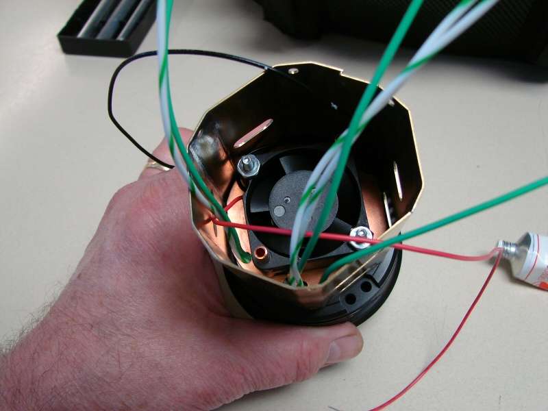
Here is the cut out heat sink and the fan is mounted on a copper plate. There is also a thermostat down in there, so that the fan only runs when the temp of the heat sink gets to 60C.
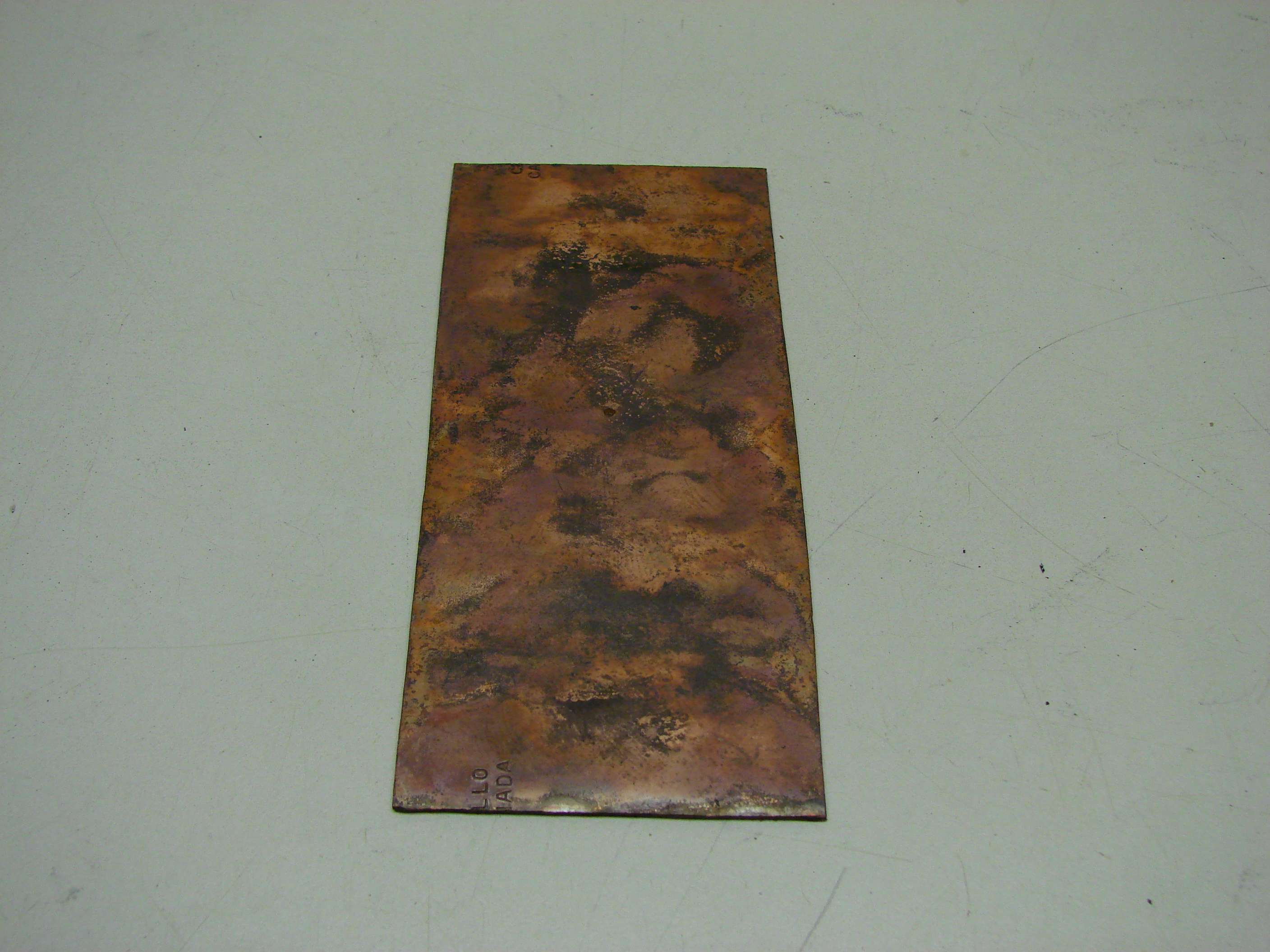
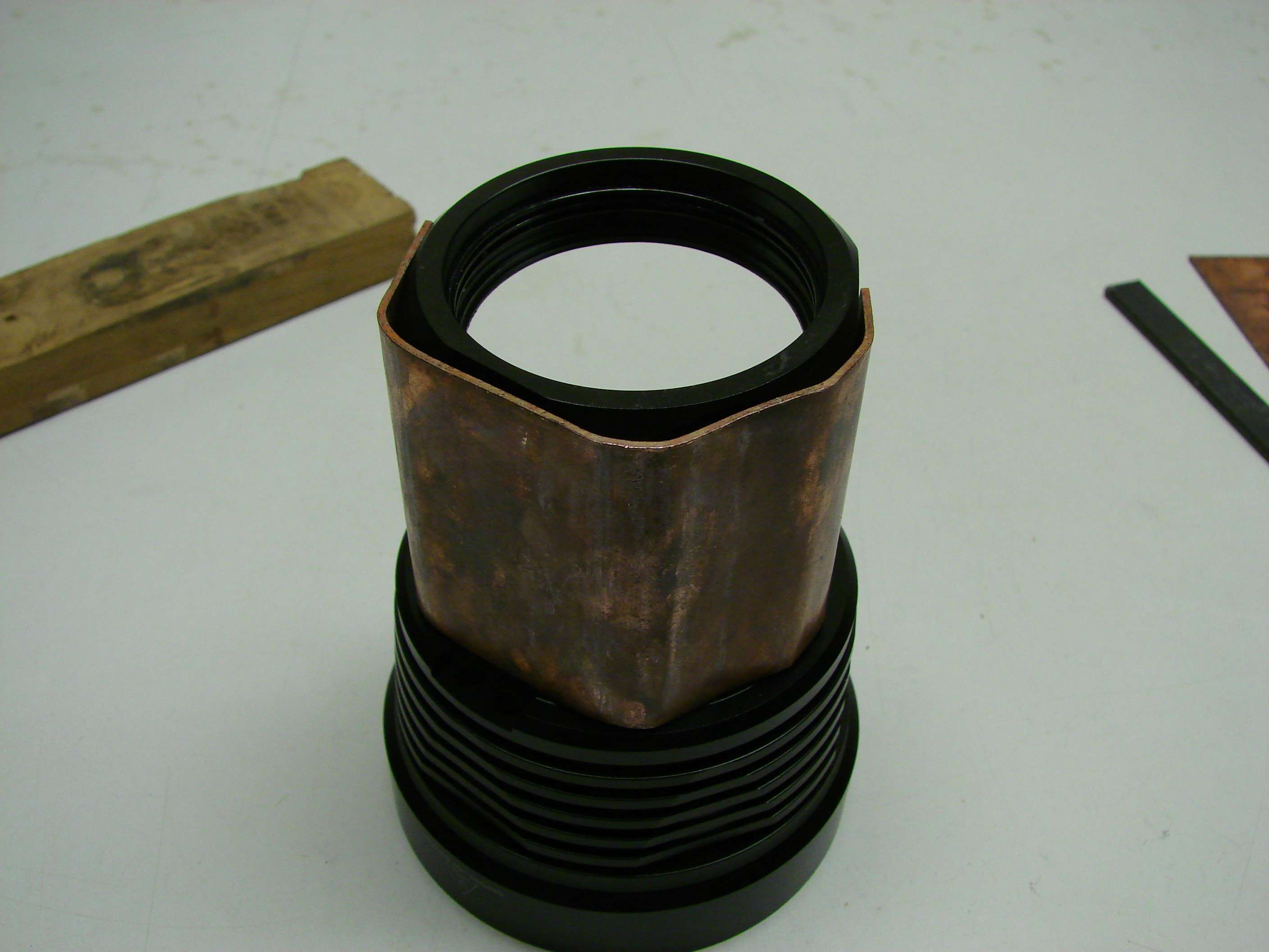
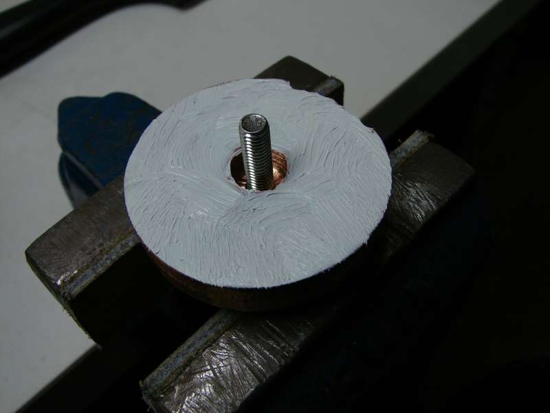
I started out using copper, to make the extension for the head. I softened it and made the bends on the table, as shown below.
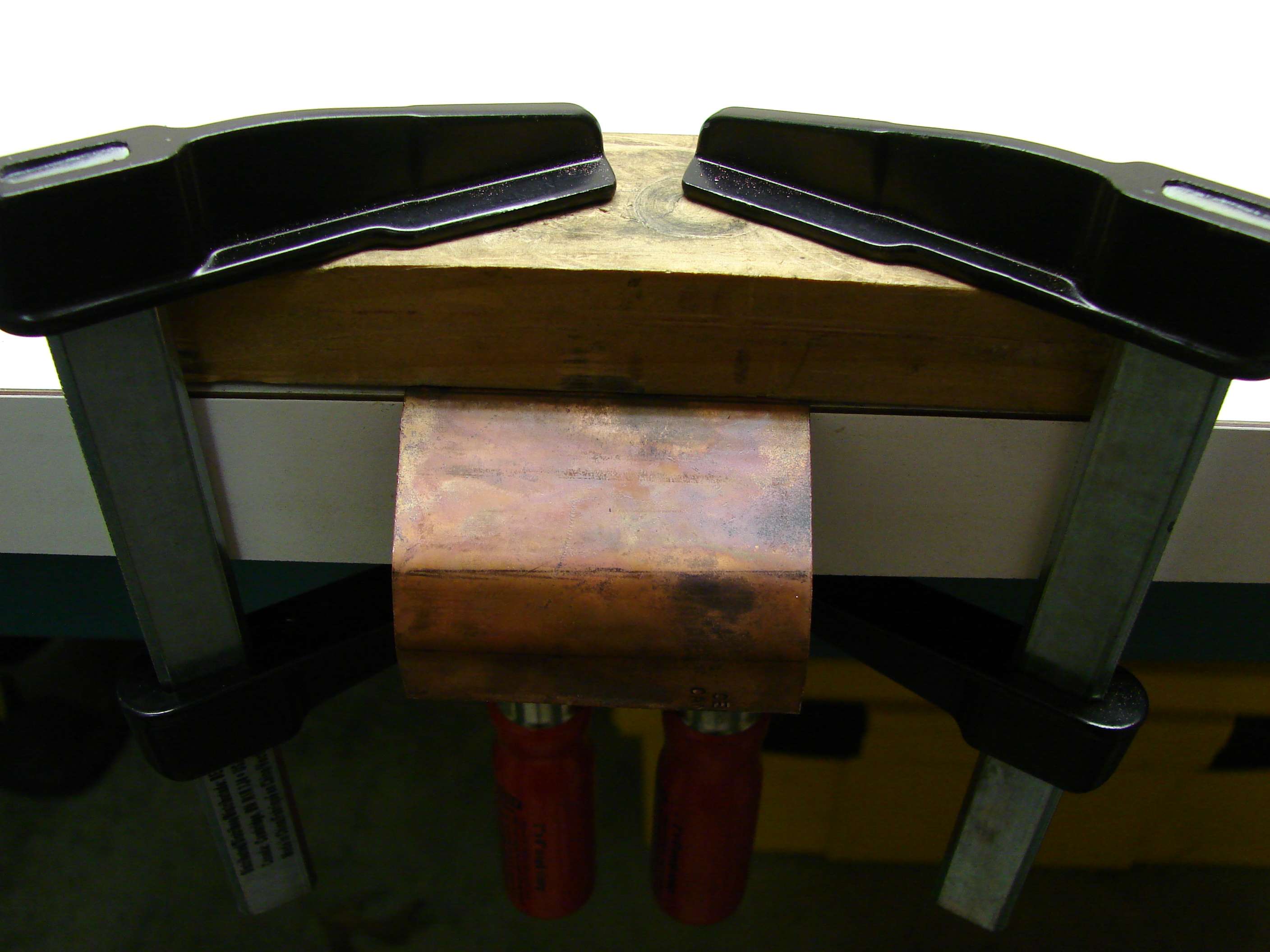
The problem was that the piece was not tall enough, so I ended up going to brass sheet, which you will see later, but this was the method for bending the brass too.
I needed two bodies to hold the 8 batteries, so I used an old SRK body and put it together with the stock body. I had to cut down both of them, so that the overall length would be right for two batteries in series.
I did the human lathe routine, to fit the two bodies together and used some JB Weld to make sure they hold. I made the SRK body look like the stock SP-03 body by removing those ribs on it.
The bodies lined up well and I think it will work.
Ok, remember I said I ended up using brass for the extension. Well, here you can see what it looked like before cleaning it up. I also made a brass sleeve on the bodies to cover up the mess there.
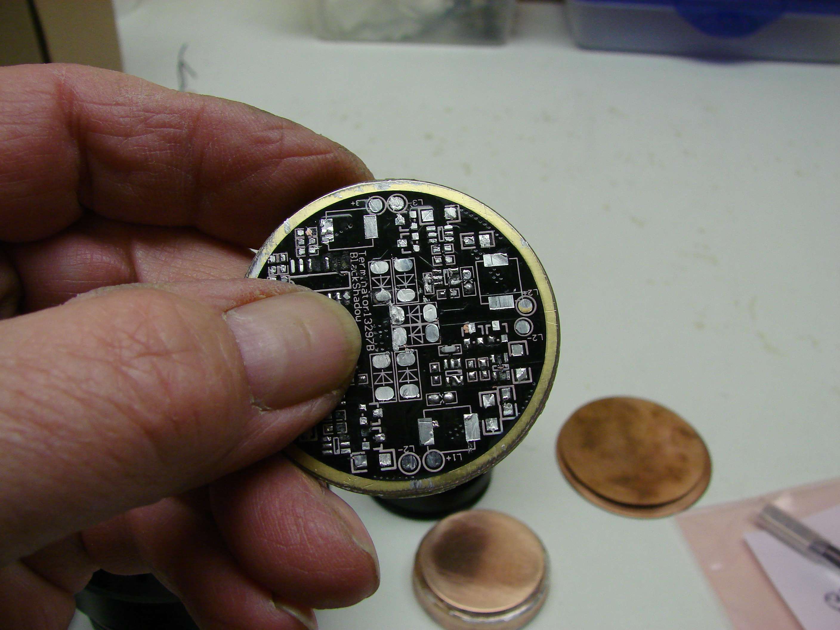
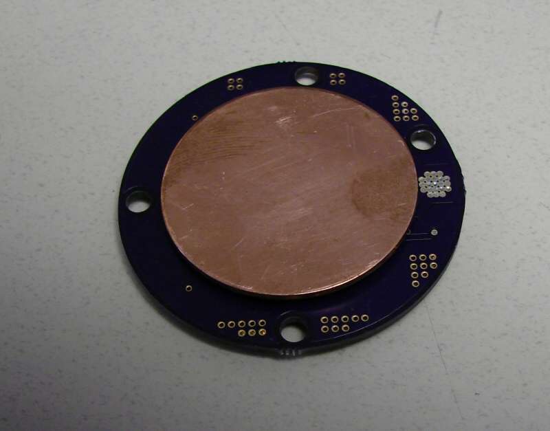
I removed the components from the stock driver and I will use it for a contact plate.
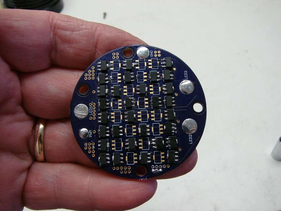
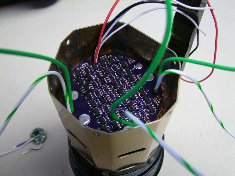
The board in these two photos is one that was designed by Mattaus, for this build. Originally, I was going to do 9 amps per led and he designed this board for 3 legs with 9 amps per leg. I ended up backing off and going with 6 amps per leg after being cautioned on my folly, by comfychair. He was right, even with 2S/4P, there isn't a cell out there that would hold 27 amps for more than a few seconds, because of the low amp hour rating on them. They just would not last at all and when the voltage dropped a little, it would just go dim. So, I went with 16 chips per leg, for about 6 amps per led. It still won't last long, but it will be better than a 30 second wonder, (I hope).
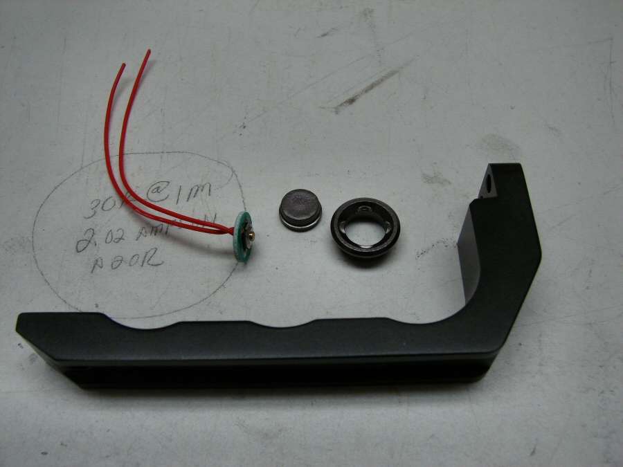
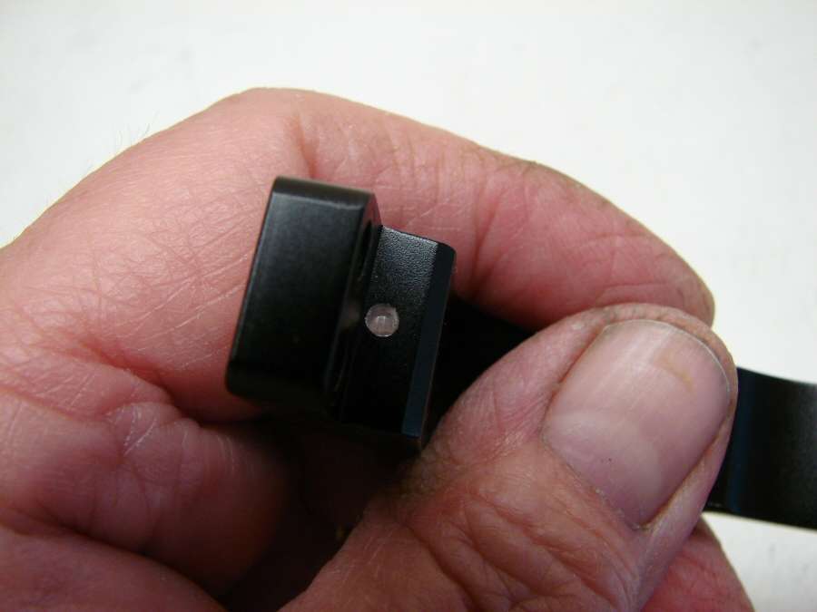
Since I cut apart the stock switch hole, I decided to put the momentary switch in the handle. Here's a couple shots of that.
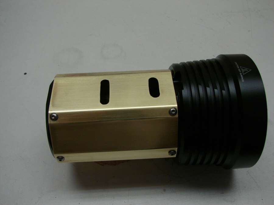
Here's a couple photos of the brass extension in place. I've cleaned it up a little and I ended up polishing with steel wool and clear coating it. The screws are stainless steel.
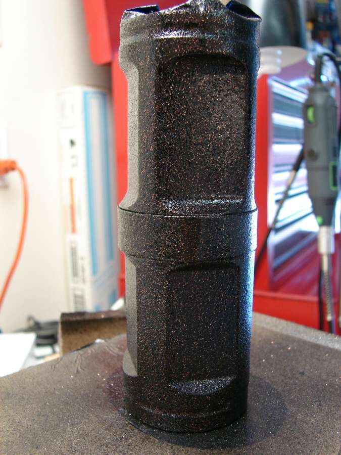
I ended up painting the body. There was no way I could clean it up well enough to leave it, so I used the same rough finish paint that I have done many times. I like the copper showing through.
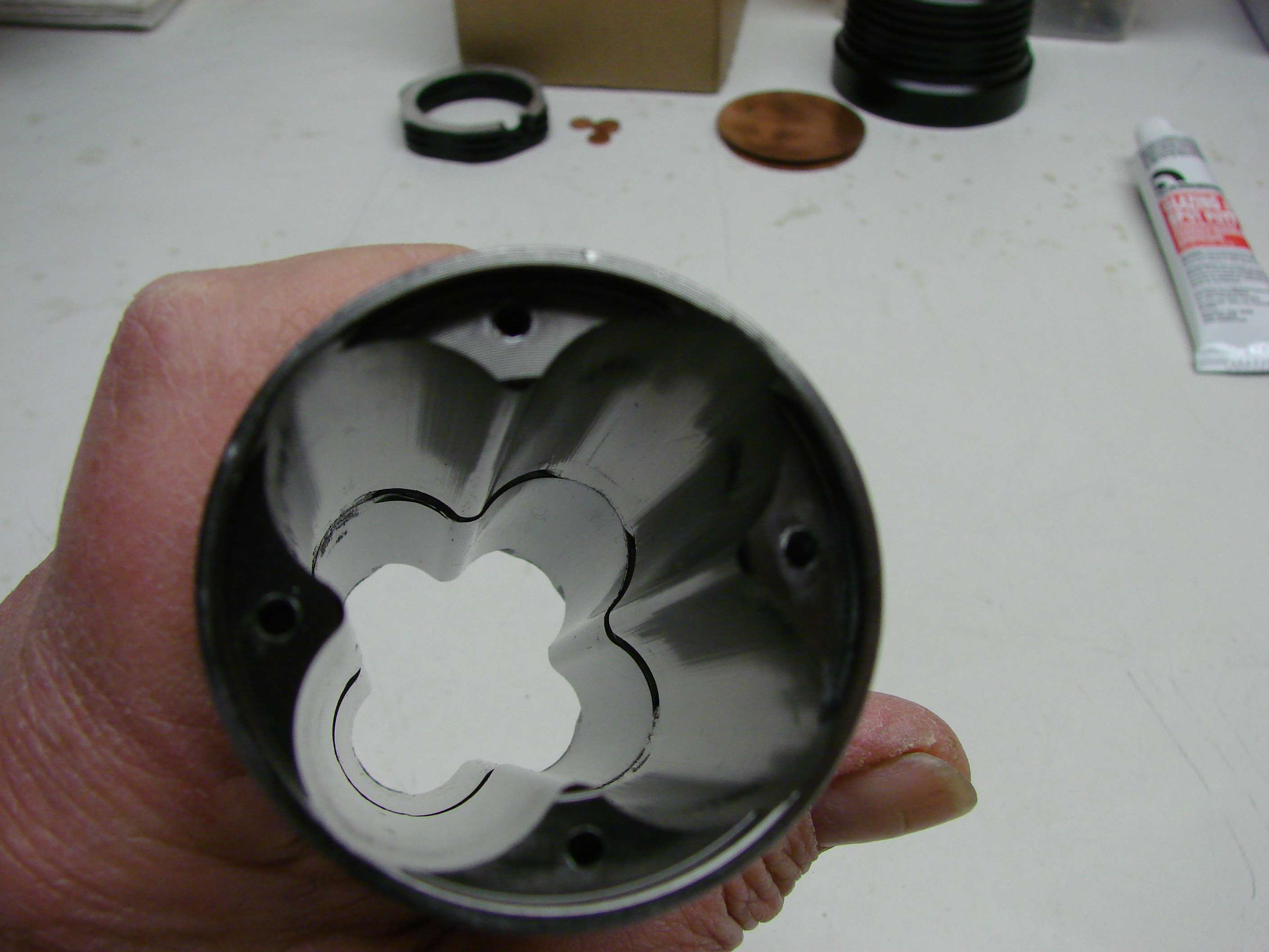
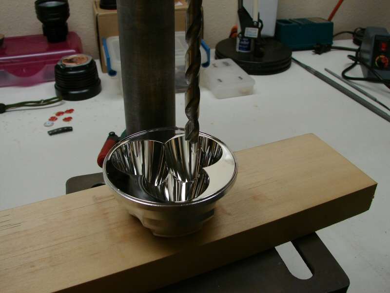
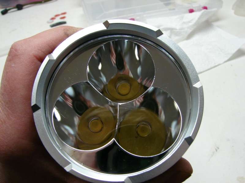
I had to drill out the led holes in the reflector for the MT-G2 leds to fit. I used the drill press and I ended up drilling from the bottom, instead of from the top as shown. I just couldn't risk ruining the reflector by doing it this way.
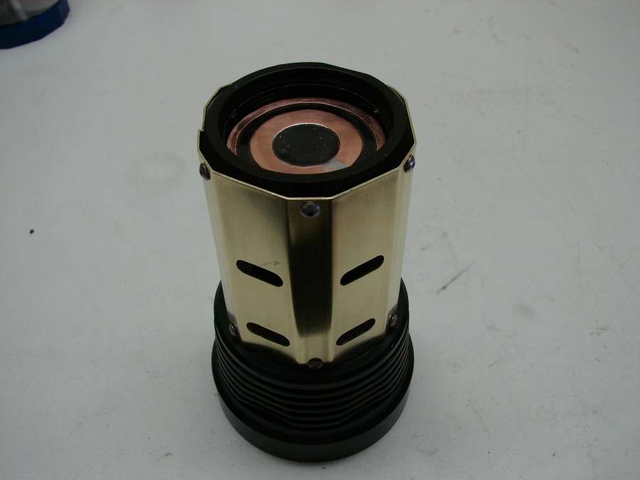
I coated the copper heat sink before putting it in the head.
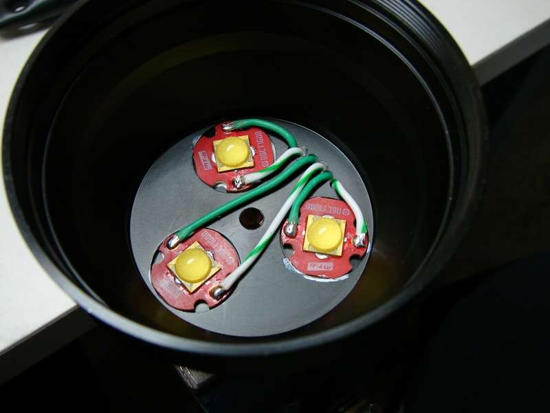
Then I wired up the leds and stuck them down in. I only used thermal grease here, since there is a bolt going all the way through the center and everything gets tightened down when the bolt tightens the reflector down into the head.
Finished product. One head ready for the next steps.
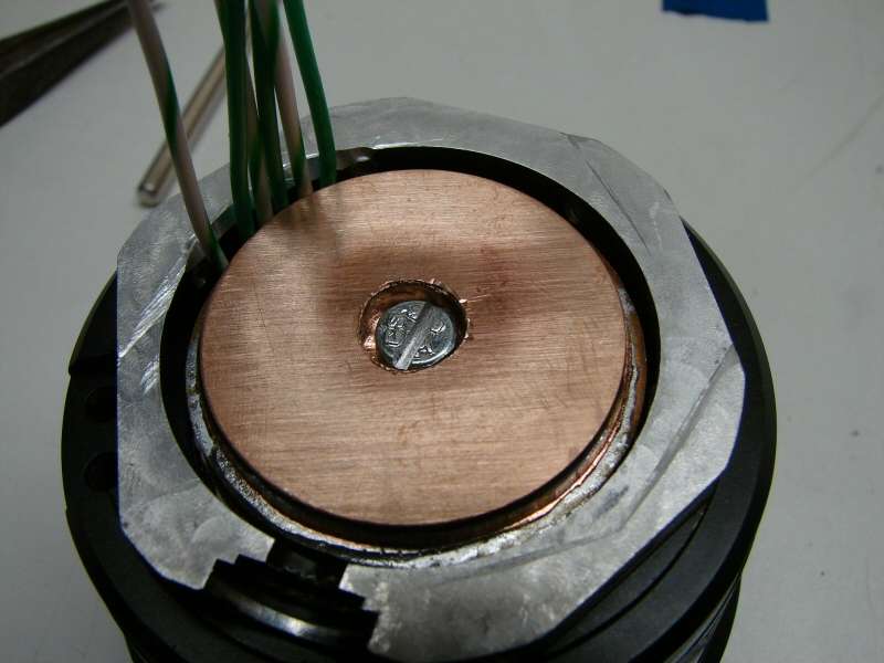
Luckily, I had a metric bolt laying around, but I had to file the head round, since it was a hex head and I cut a slot in it, so I could use a screwdriver to tighten it down.
The aluminum heat sink is glued down and the fan is in place.
The brass extension is in place too.
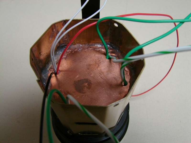
The top plate is copper and it is silicone in place. Hopefully it will help to seal a bit, so any water won't run into the driver area, but this is Not a water resistant light. It would be best to not expose it to rain.
---------------------------------------------------------------------------------------------------------
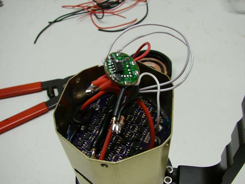
I managed to get the slave board in and it's wired, but now I don't have a good master lying around, so I need to wait a few more days. Sorry.
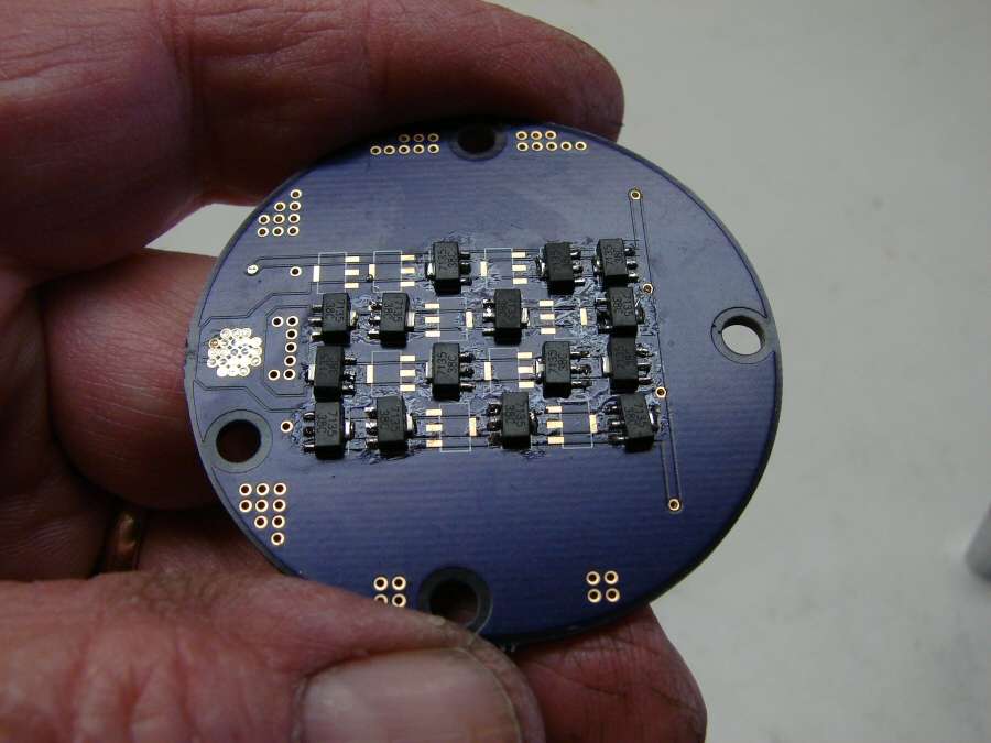
I put a copper disc over the bottom side of the board, glued to the 7135 chips with AA. It might help a little with heat... or not.
I will put another disc or rectangle on top of the board, after everything is wired up and tested.
---------------------------------------------------------------------------------------------------------------------------
Last time, it looked like it was mostly done. Well, the driver came in from RMM and I hooked it up. It almost worked! Two leds worked as advertised and the driver cycled with the switch, but the third one just came on high and wouldn't cycle... Shorted to ground. I tore everything apart and found the reflector was pressing on the led substrate, causing the short.
Sooo... Time to make changes.
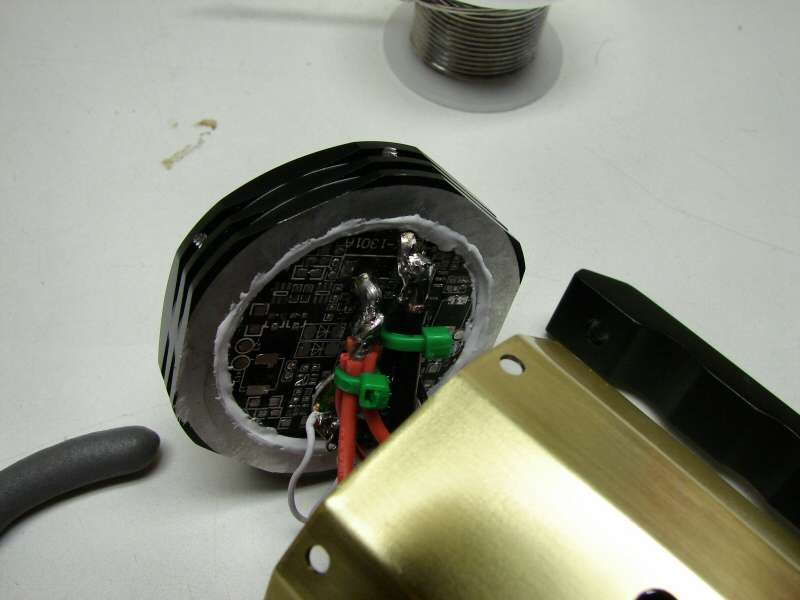
I put kapton tape on the reflector. See, most of these multi reflectors have metal between the led holes and that acts as a stopper. This one does not. The led holes rest right on the substrate. When it was an XM-L, it rested on the centering ring, but with the MT-G2, it rests on the substrate.
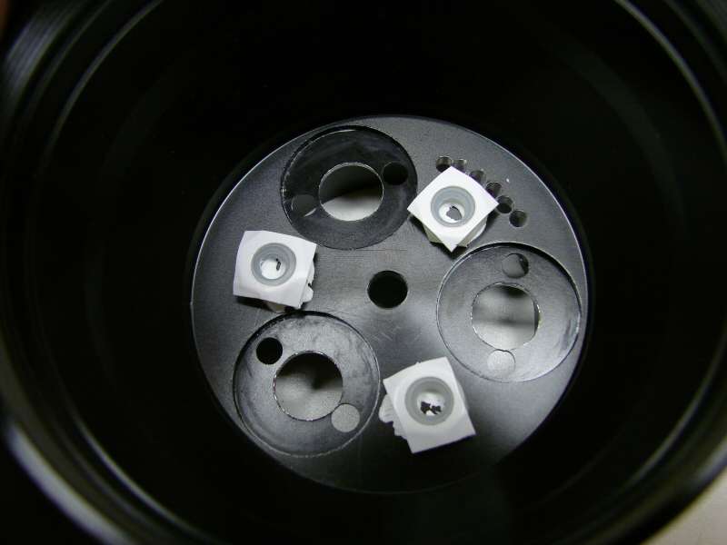
I also added three stoppers, so that the reflector will not compress too hard on the substrates.
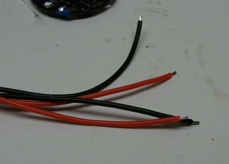
The third thing I did was to switch to silicon coated wires. The Teflon ones were just too stiff to work well.
Now, I can reassemble everything and see how it goes this time.
-------------------------------------------------------------------------------------------------
Finished!
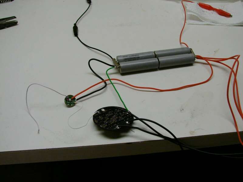
I don't have 8 batteries for it, so I am testing with 2S/2P Panasonics
And it works this time!
Final wiring
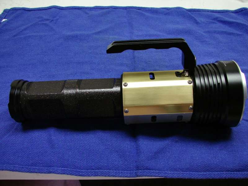
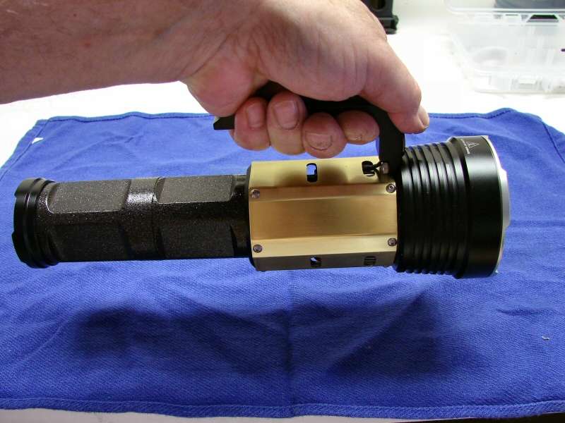
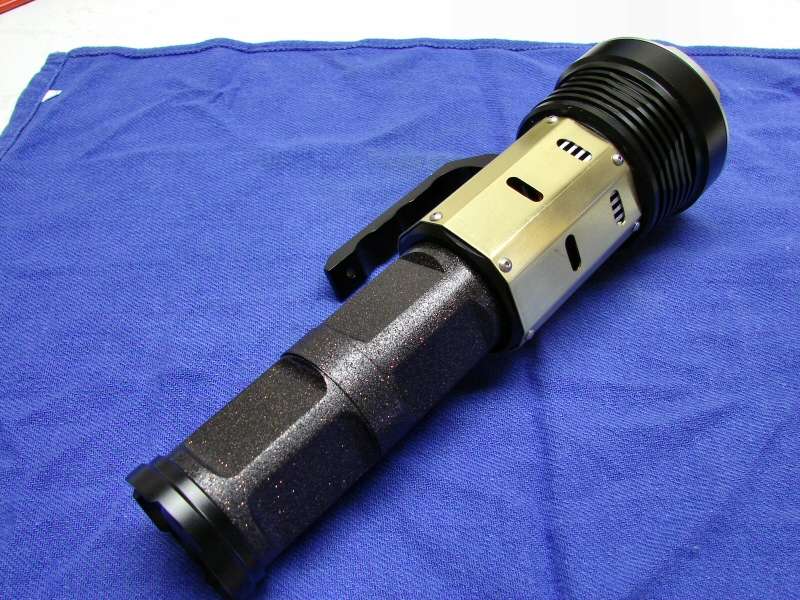
Shots of the finished light. It's a very strange looking light.
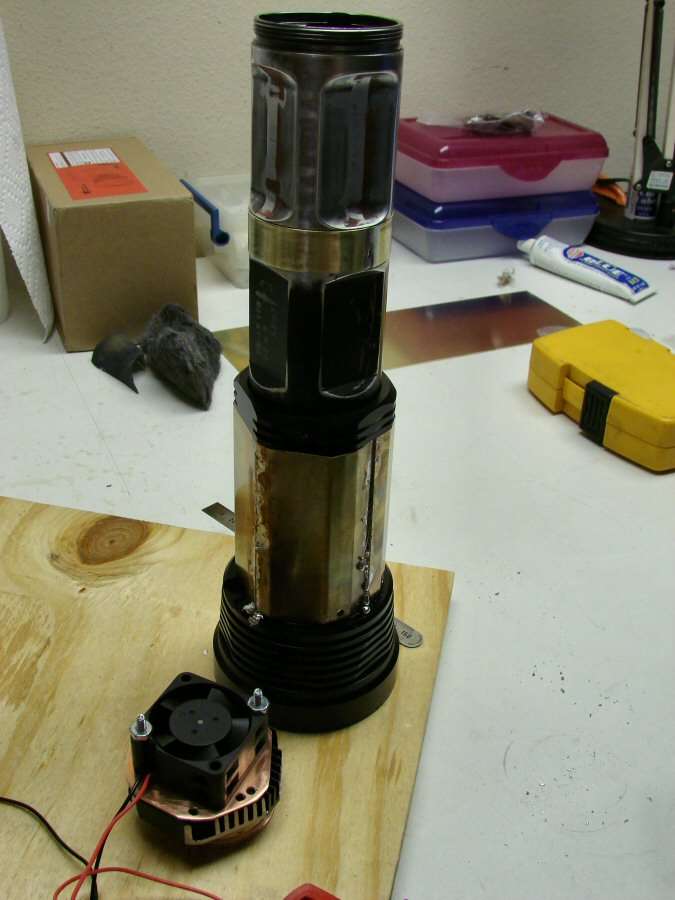
As I said, I don't have 8 matched batteries, but I did have 8 total batteries, so I tested them. I had to get it hot to make sure the fan works. The fan does work, but I wish I had used a 40C thermostat instead of a 60C. The head gets hot! Very hot! The batteries start to gim before the fan turns on, but it does turn on.
Almost a total success, but at least it does work. Guess I should be glad for that.
05-17-14 I am going to tear it down and use a lower temp thermostat, so the fan kicks on sooner and I need to tackle a ground issue, so it ain't over till it's over, but there's a beam shot in post #1 to tide y'all over.
Listen to the light, 
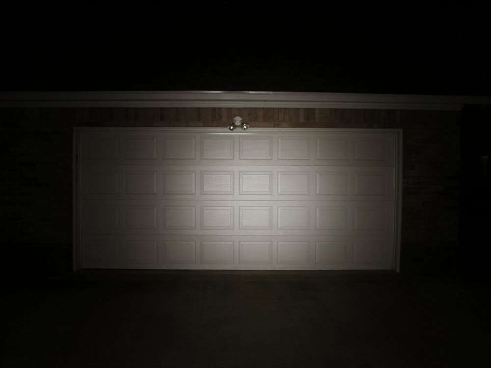
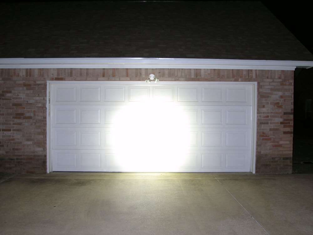
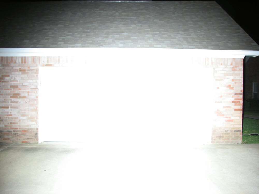
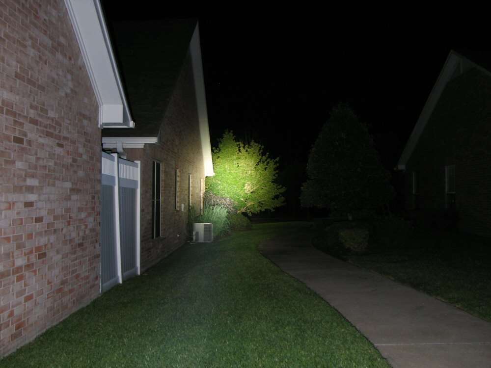
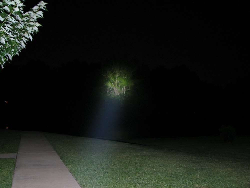
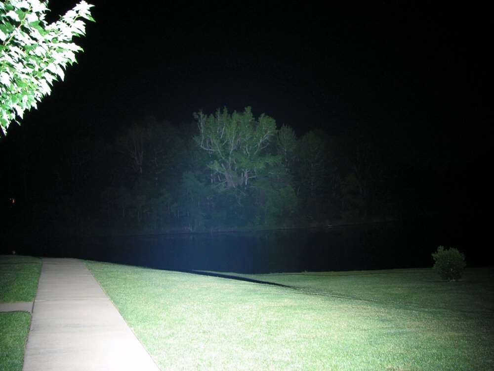
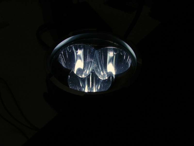
Beam shots will be done tonight (6/4/14)