As of today, June 7th, I completed the "Super Shocker" 3rd place contest prize award light. In summary:
BTU Shocker - 3 modes, "direct drive" high amps, de-domed XM-L2 U2 1A's
Components:
- BTU Shocker host donated by RIC at CNQ
- additions of a 5A, 3 mode driver bought from LCK-LED here, with resistors bridged
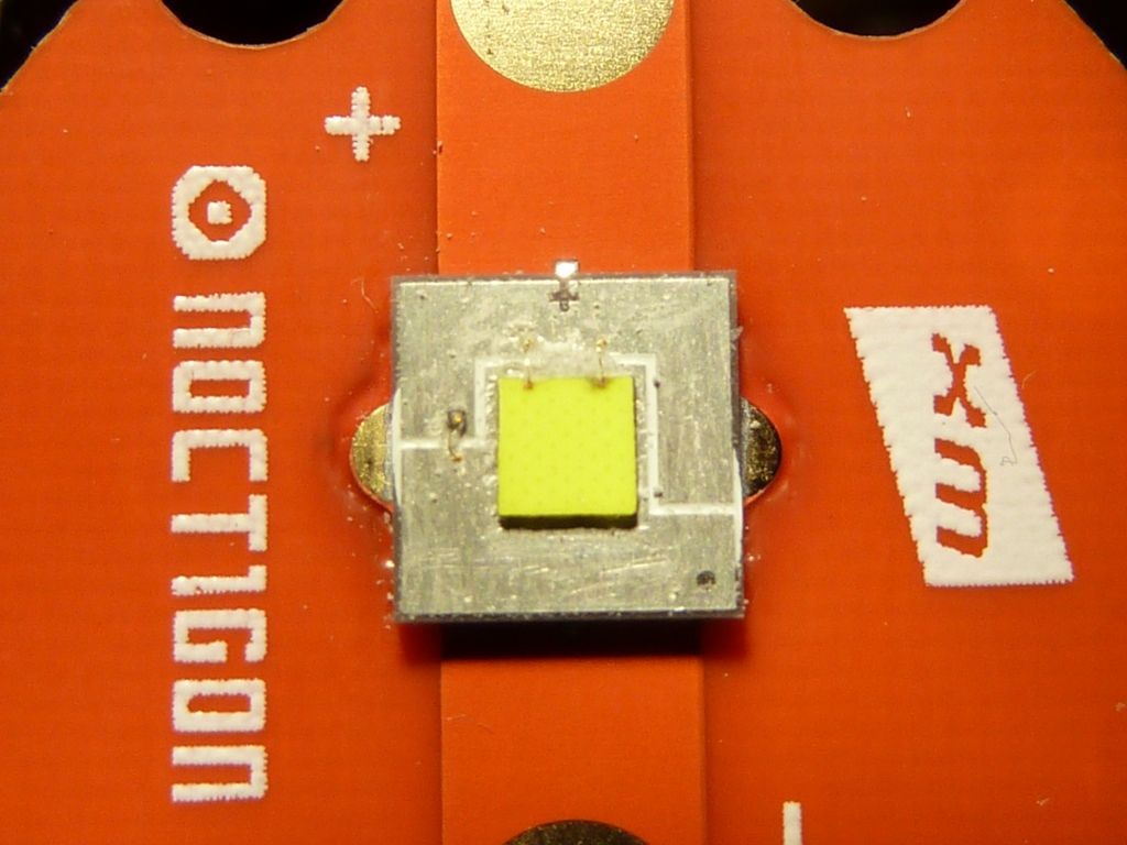
- three XM-L2 U2 1A LED's on Noctigons, bought from Hank at IOS, de-domed in gas after about 2 1/2 hours
I'll let the pictures do most of the work, but will supplement with commentary.
-------------------------------------------------------------------------------------------------------------
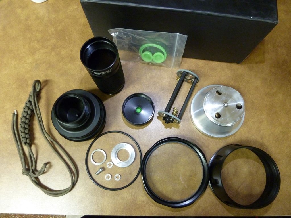
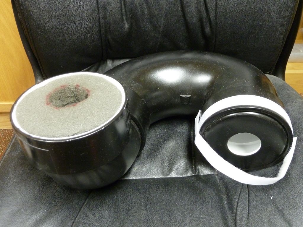
Here's all the pieces of the Shocker host, provided by RIC at CNQ. It's a robust host - lots of metal (and weight), very easily moddable - no glue anywhere, large pill, thick pill top, nice AR lens (I believe it's pretty good based on before/after measurements when the AR lens was added after the light's initial release):
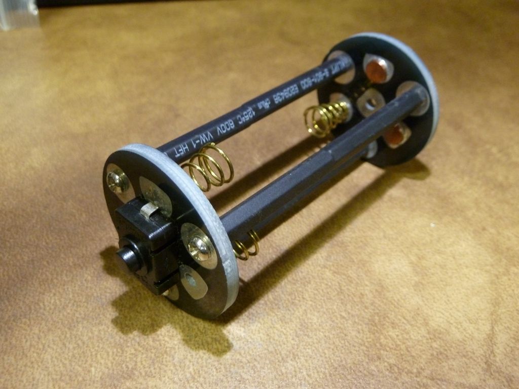
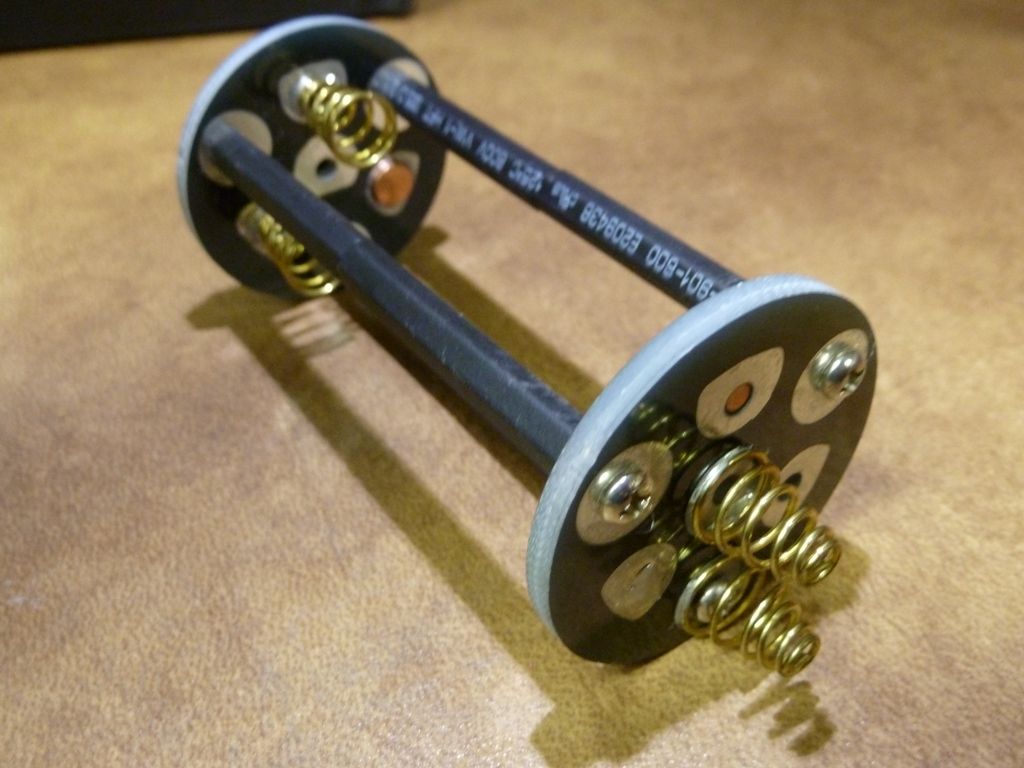
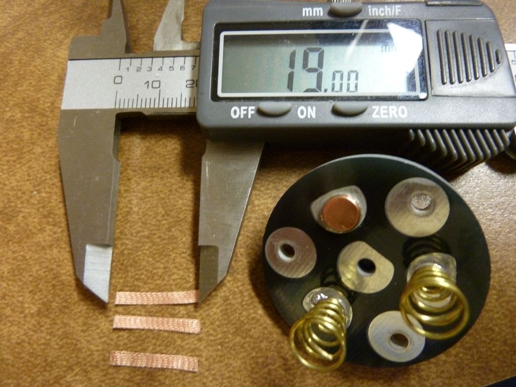
Here's a close-up of the stock carrier. Again, easily moddable, comes apart easy, large soft springs:
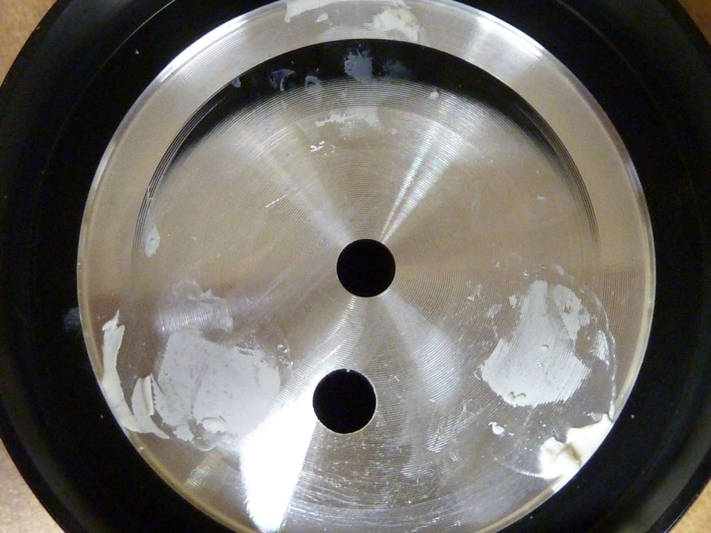
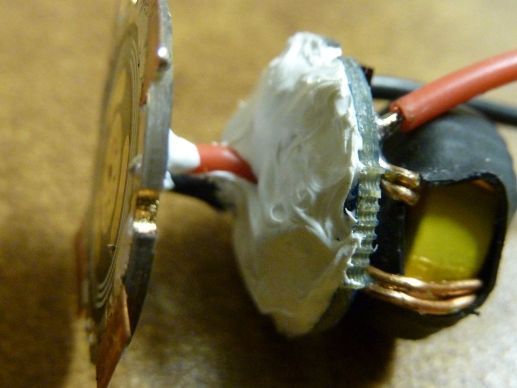
The pill top, as delivered, is obviously used, or rather, the emitters were taken off. Clear evidence of the standard epoxy, soft style. Note the overspray of black, or maybe a poor tape job? All this will be cleaned up - no matter:
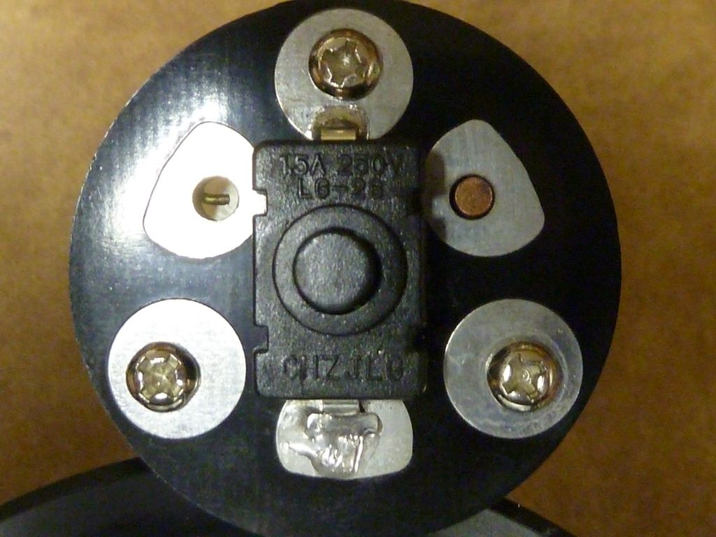
The standard Shocker switch. I'll be leaving that in - I haven't had problems with them yet:
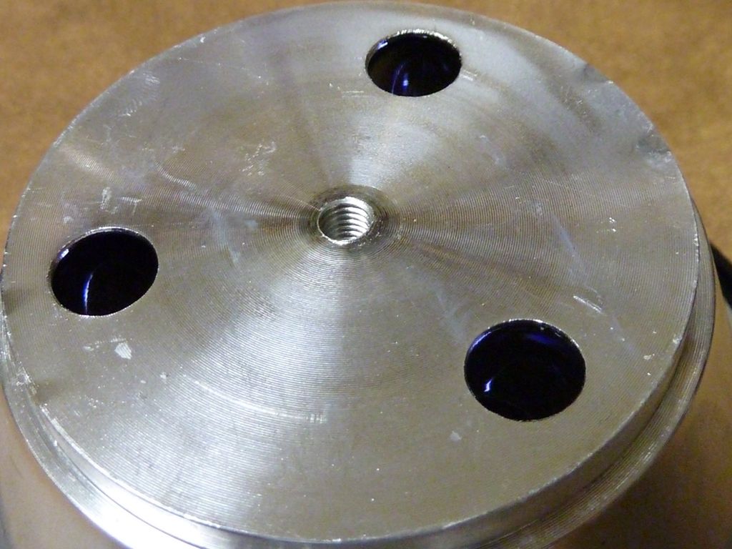
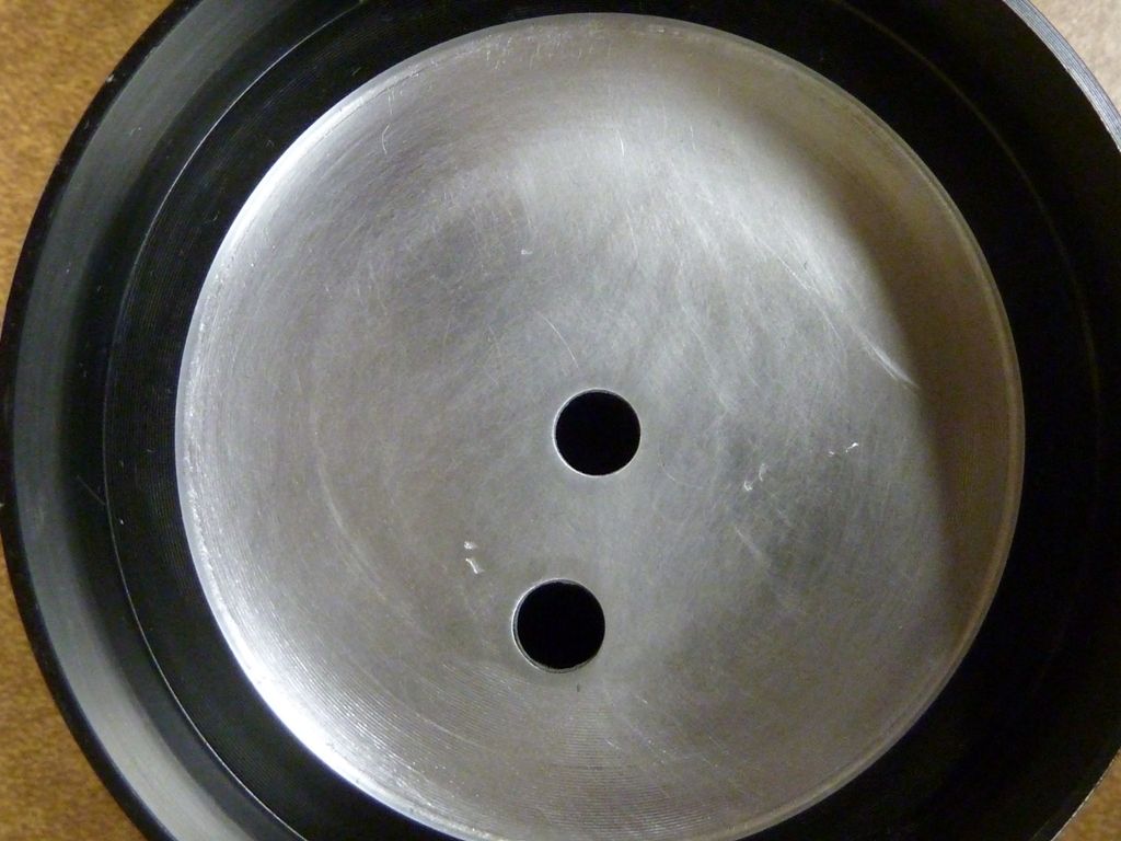
The reflector under side - bad news is it's flat. The reflector is one solid piece of aluminum though. I would rather see 2 screws instead of one:
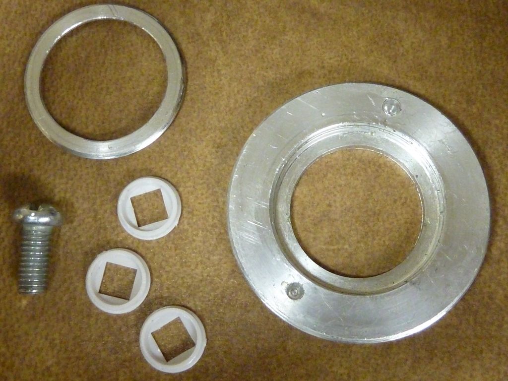
Here's a close up of the pill parts. Those LED alignment pieces are rare. I can't find direct replacements. I asked/ordered some from RIC, specifically for the Shocker, but the ones he provided were a different size. It's important these pieces are an exact fit for the reflector hole (I mean exact), otherwise, if it's smaller, there will be slop room and the LED's will be very difficult or impossible to center:
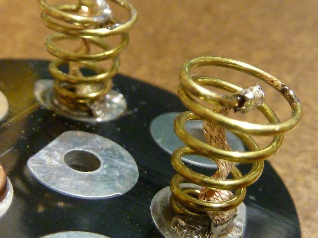
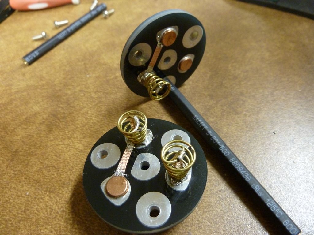
Ok - here we start on the mods, carrier first. I'll use a good quality copper braid on the battery springs, and 22 AWG wires on the driver contact springs:
The top end of the springs are bent in for better battery contact and for folding the braid over:
Pre-curling the braid ends:
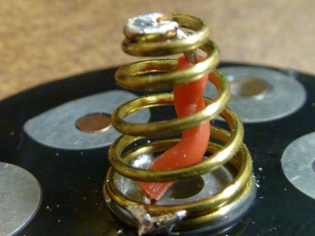
The 22 AWG wires for the + and - spring driver contacts:
One trick shown here is to use the S or snake shape of the braid. This ensures the braid will bend properly with spring compression, with the least amount of pressure to weaken or break the braid, and still allow full compression:
Rough edges on the top are filed down. With wires, same rule: pre=shape the wire so it collapses properly with spring compression, and doesn't interfere with full compression:
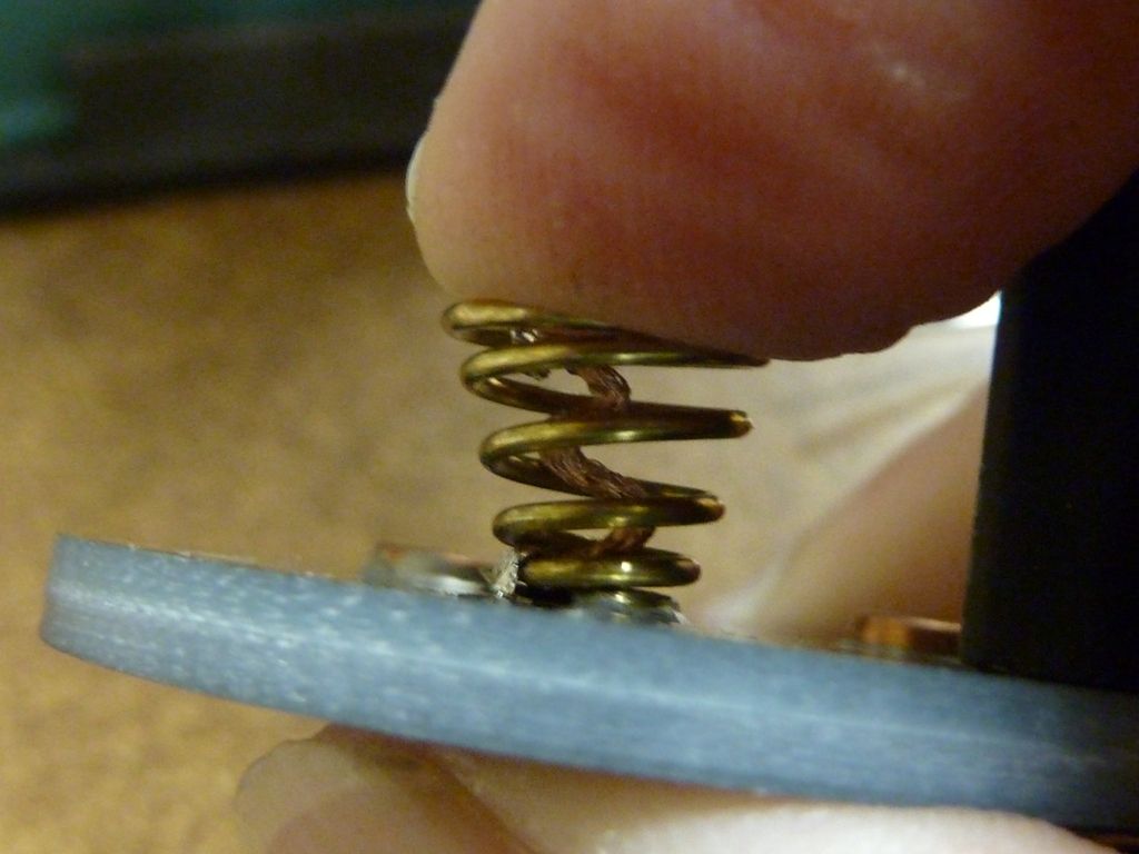
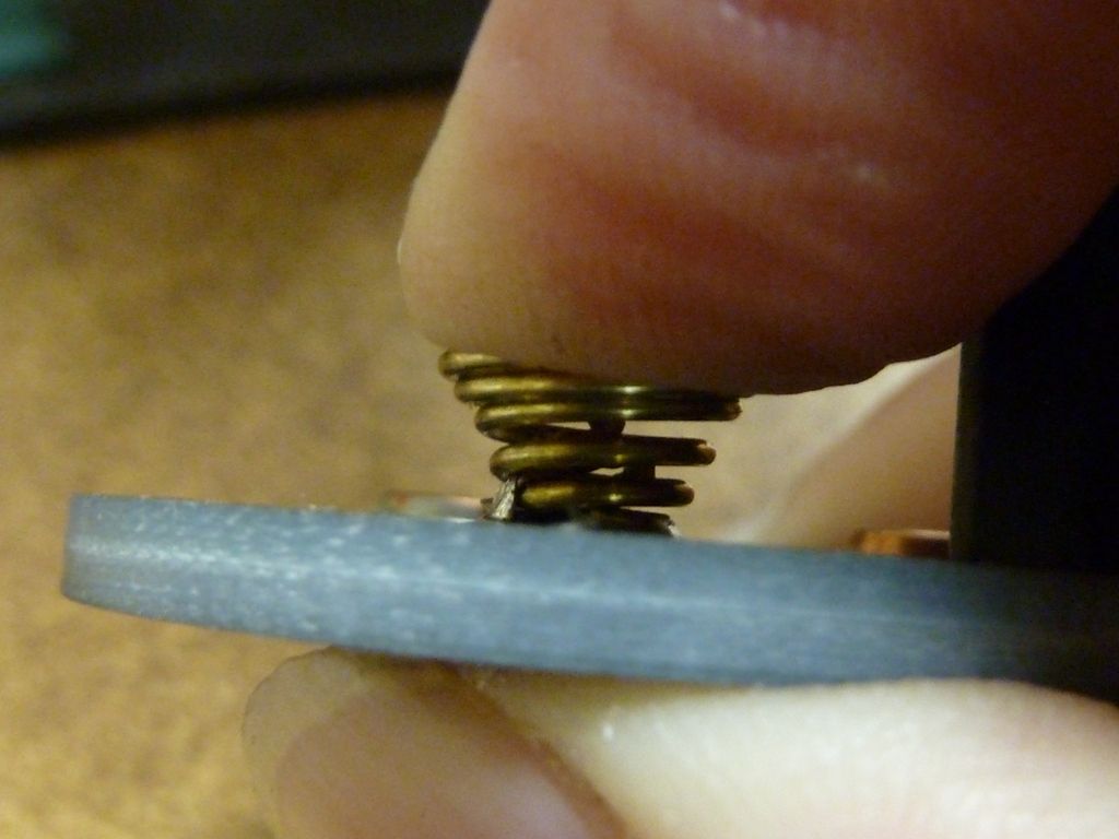
Showing a test:
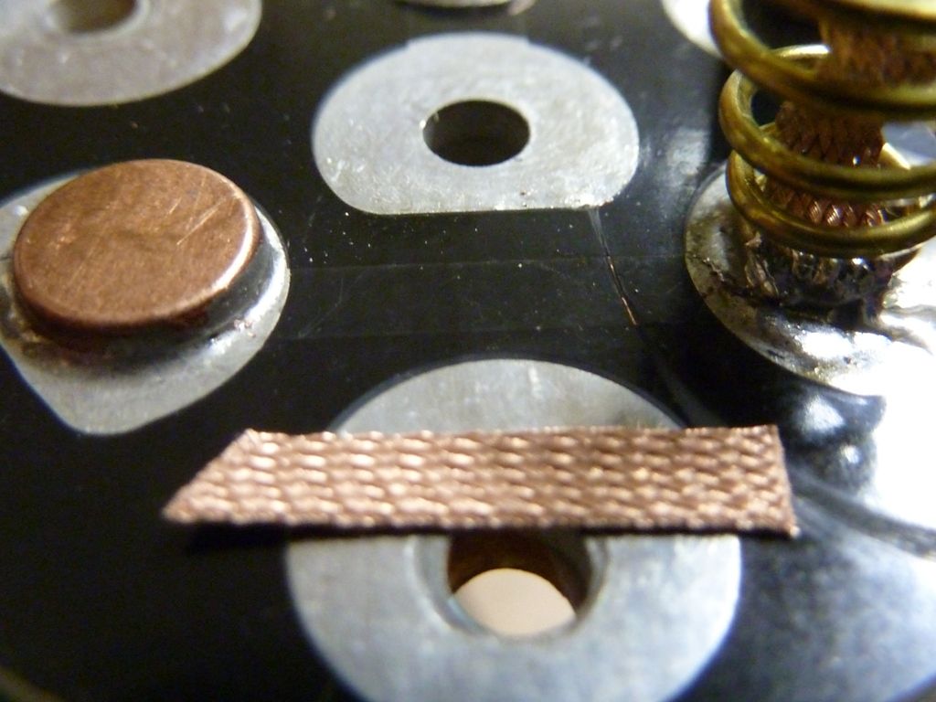
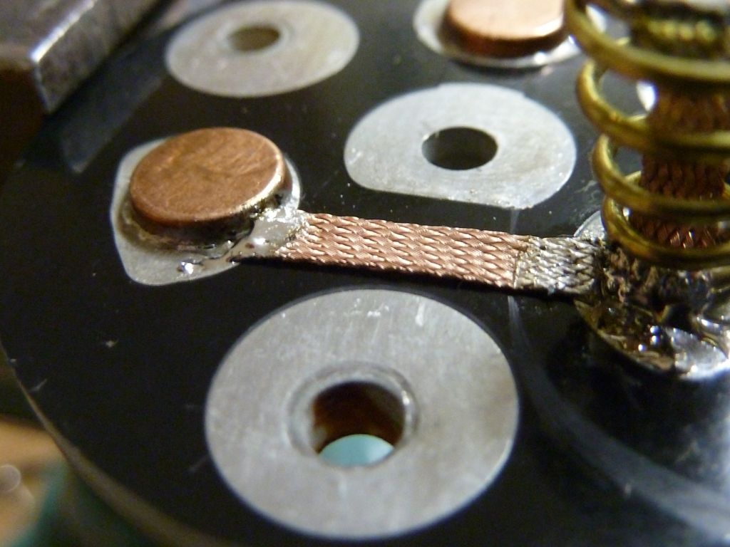
If you look carefully at the traces of the carrier, you will find 3 longer runs. These are a potential source of resistance. So, bridge those traces with something much more beefy:
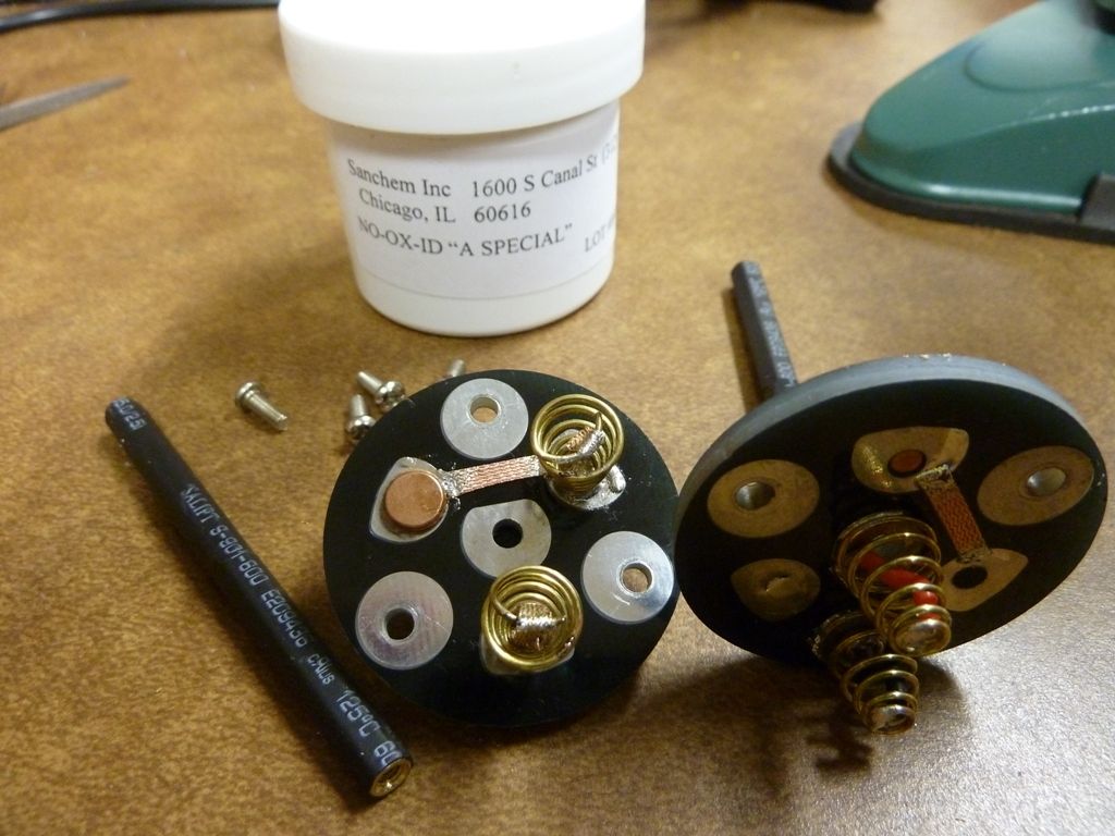
I used NO-OX-ID from IS on all the screw and brass rod connections. Also light coating on the spring and copper pad contact points:
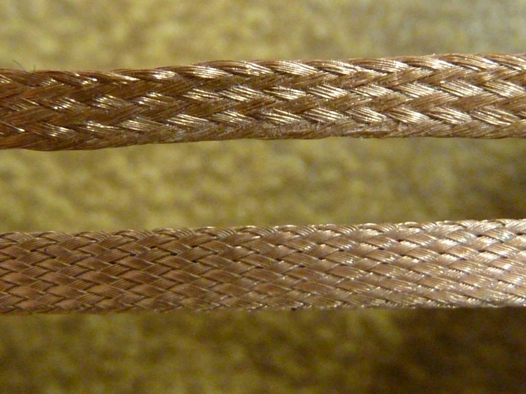
This is the copper braiding I used. Much better quality than the standard Chinese sourced braid. I've had this a while and didn't realize how tough it is. The gootwick will easily break and shred while this stuff doesn't seem to be bothered at all from bends. I only started using this recently, and now will never go back:
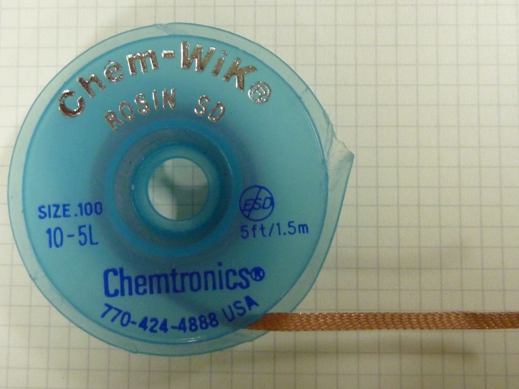
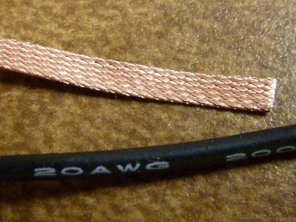
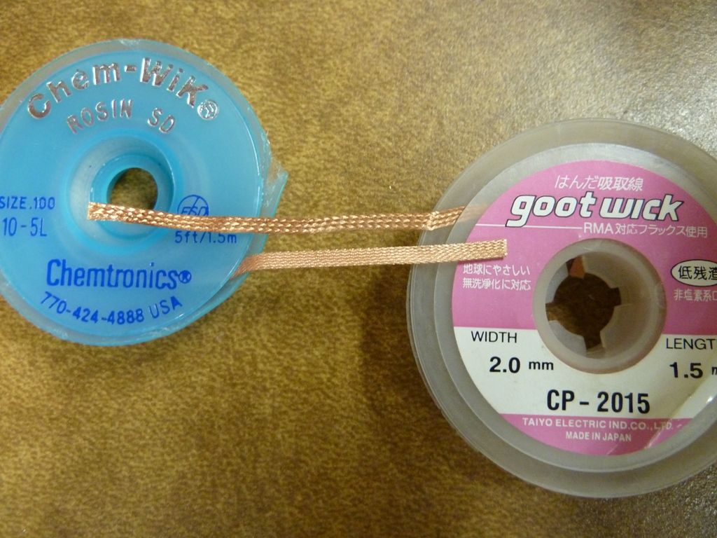
The gootwick is on the top, and the Chem-Wik is on the bottom. Notice the tight weave in the Chem-Wik? Also, I always soak the braid in Isopropyl alcohol first before using:
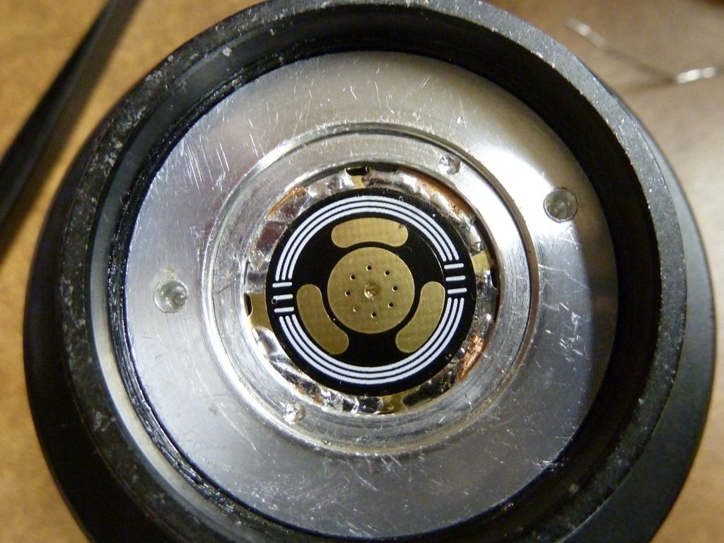
Here's the pill top after fully prep'ing. It' sanded by hand:
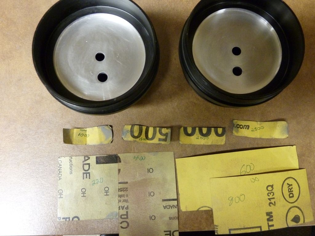
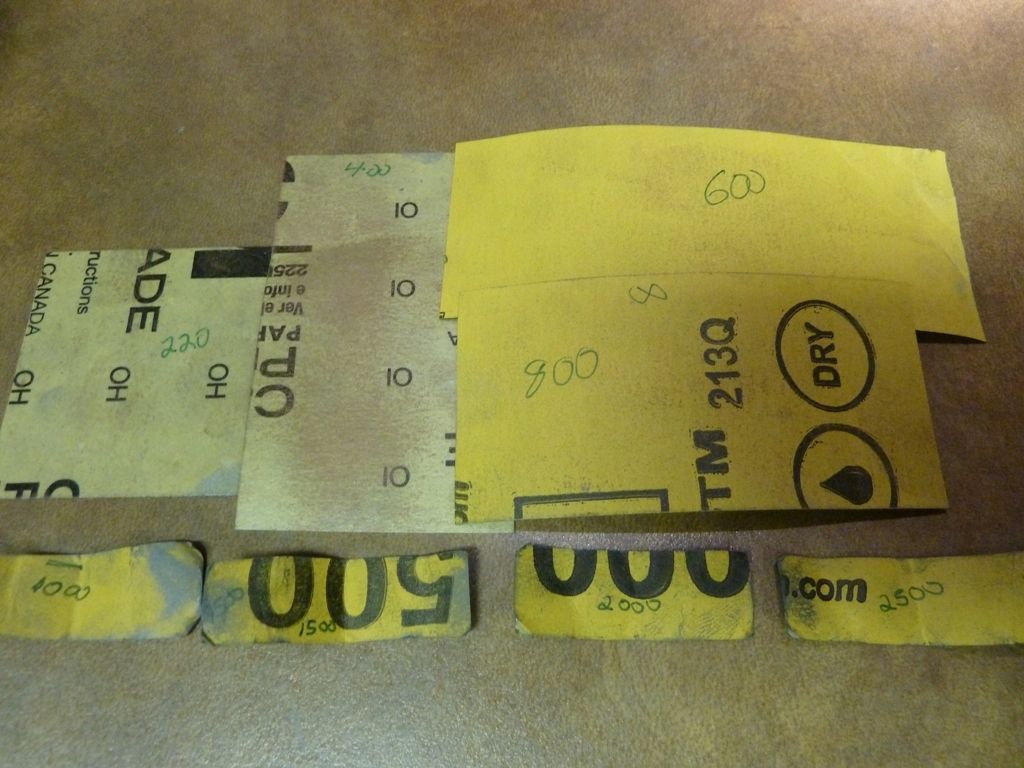
Shown is all the GRIT paper I use, starting with 220, finishing with 2500:
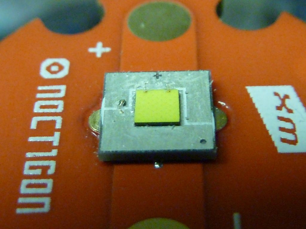
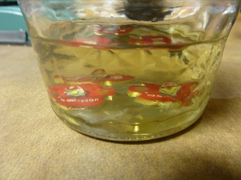
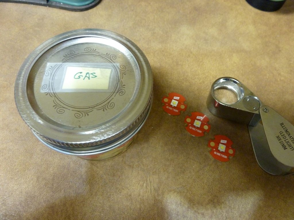
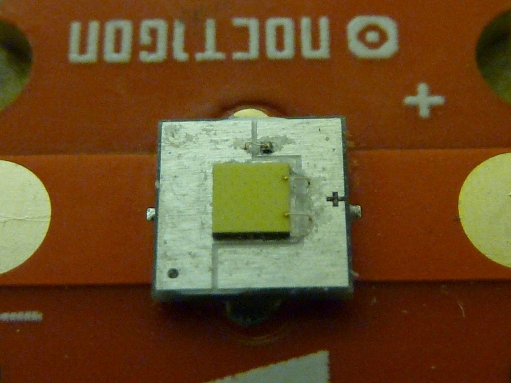
Here's views of one of the de-domed emitters. I soak them in gas, in a mason jar, for at least 2 hours, then push the silicone cap off, if necessary, and use a magnifier loop and toothpick to clean it up. I also use isopropyl alcohol to clean the gas off, squirt it directly on the LEDm and squirt it to clean off the debris taken off by the toothpick.
Soaking:
The loop shown below was bought from FastTech. It has a double light built in, but I don't use it. I'm using a NiteCore HC50 headlamp now which works out great on the 3rd mode (of 5).
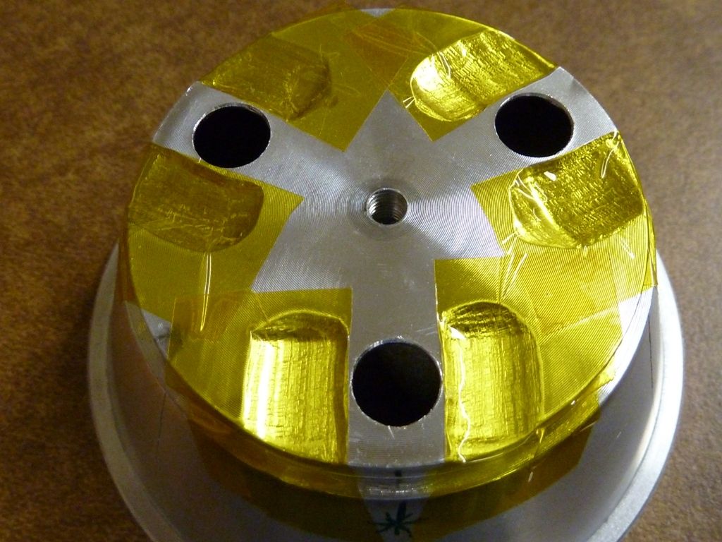
Ok - next phase: dremel out notch's to make room for the wires on the MCPCB's. This setup was an evolution: clamp to secure it well, a lid gripper for soft contact to the bench top, tape to cover the holes to keep dust/fragments out of the reflector, sand edges smooth when completed, use a rounded cutting bit. A squared off bit may cut too deep next to the reflector, and actually break thru (yes - it did happen...). This rounded cutting bit was bought in a kit of assorted shaped cutters from FastTech:
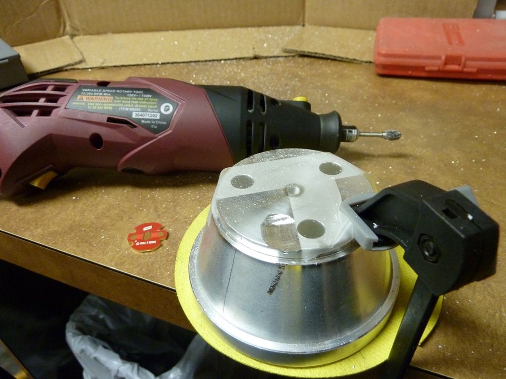
Well, not really a dremel - Harbor Freight special. Cardboard to keep the fragments contained:
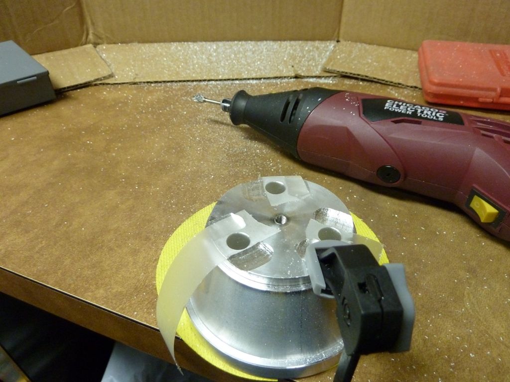
Now for the LED alignment pieces. Too thick, also can block output. I'm not sure how much difference this makes for certain, but I decided to take this down more than I've done in the past and I think it paid off big time. With de-domed LED's, you always have a black hole in the beam, just depends how far away from the wall you have to be to see it. With this Shocker, the magic #' is like 8-10" from the wall -- tightest I've ever gotten. So, here's the stock piece:
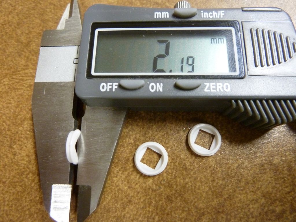
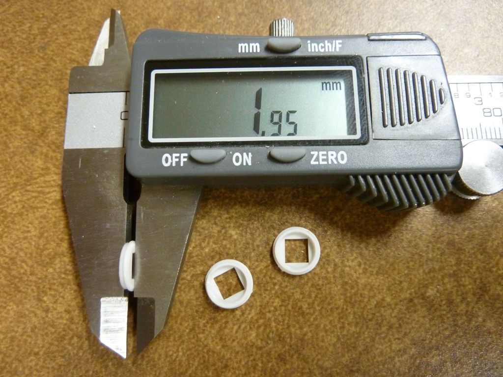
Below after sanding. I took it down to 2.05 mm from sanding the top of the pieces, then took it down 0.10 mm further from sanding the bottoms. Everyone likes their bottoms sanded:
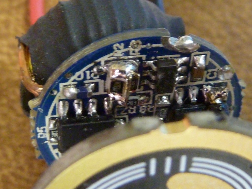
Now for the driver. I use a resistor lead wire for the bridging. The 22 AWG stock LED wires will be replaced with 20 AWG, and the thinner wires to the contact board also replaced with 20 AWG. Stock driver:
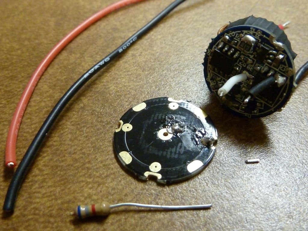
After the wire and jumper mods:
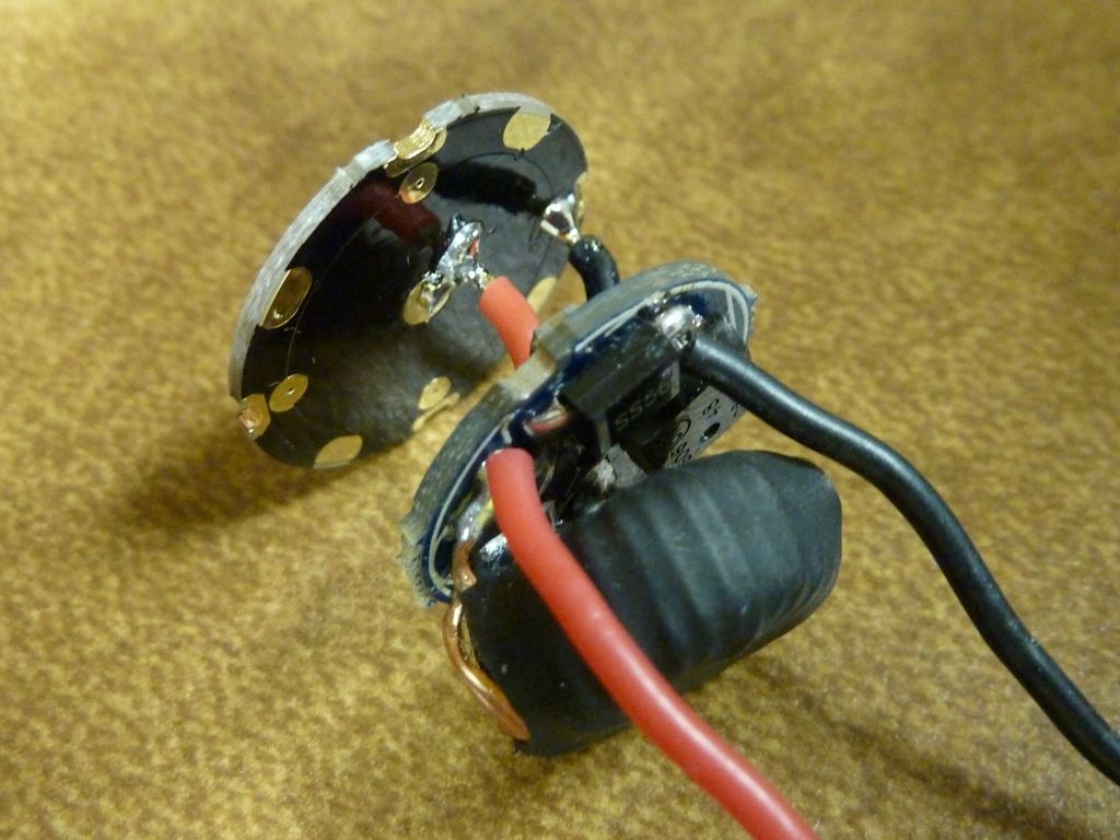
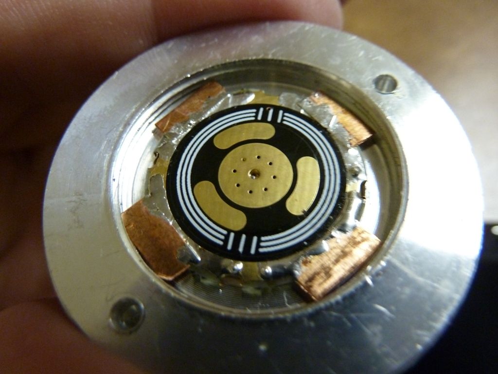
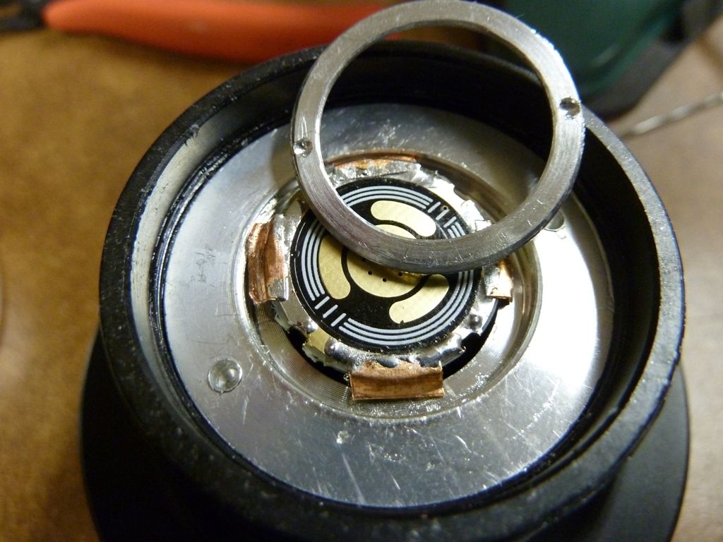
The stock driver contact board is under-sized, and I could not find a proper size contact board for the Shocker, so, I've been doing this copper sheet metal trick to extend the edge to have something the retaining ring can thread down on to. It seems to hold up well. The large aluminum ring screws into the body pill, and the driver goes through it's center hole. The small ring holds down the driver, but it had no guide holes, so, I drilled my own, using a small drill bit in my cheap drill press from Lowes. Actually I used to do it with a hand drill, but the drill press is so much easier I've learned:
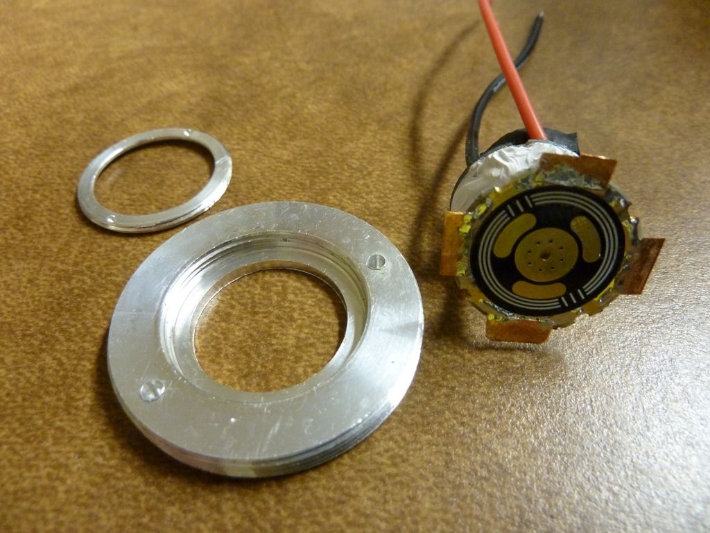
here you can see it fit in place:
Here I used Fujik epoxy, not grease, to pot the driver. I'm hoping this helps. The driver comes with a thermal pad, usually, but I think the potting may be more effective - not really sure...
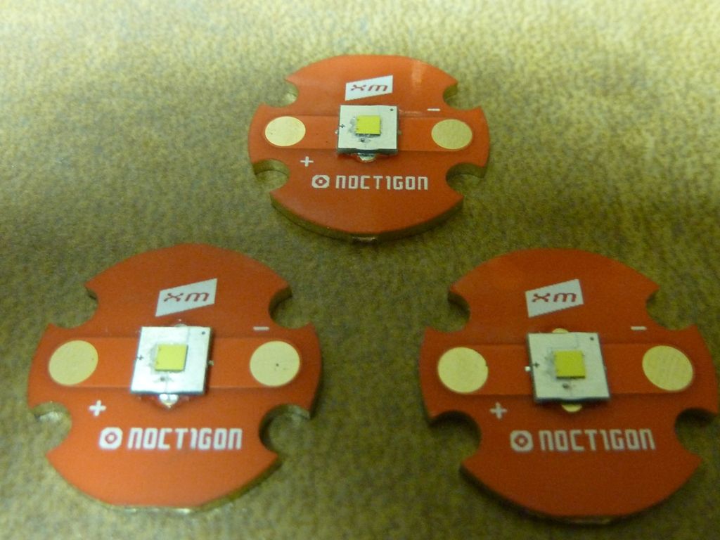
The 3 LED's, de-domed, ready to go:
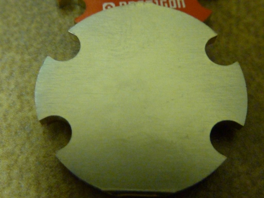
Backsides lightly sanded with 2000 GRIT paper, just enough to take off any burrs or to take down material from scratch's, etc. I find almost always there's something that needs to be taken down from sanding. You can feel it, and see it from the sanded pattern. There's a gold layer that comes off quick because it's thin, then the nickel layer is exposed. Not sure I like this over the SinkPAD's that seem to be more pure copper, but the finish is smoother on the Noctigons:
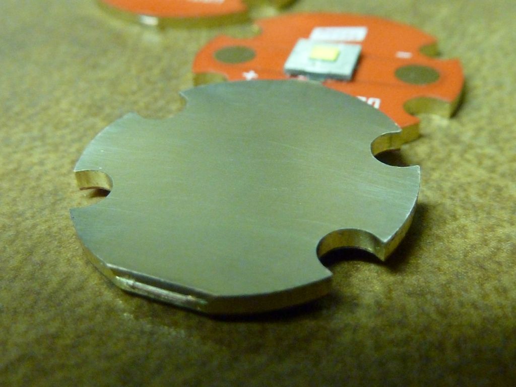
Another close-up:
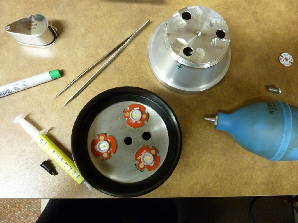
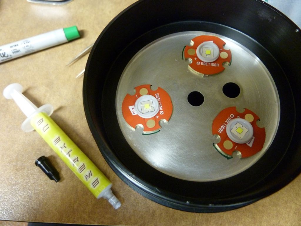
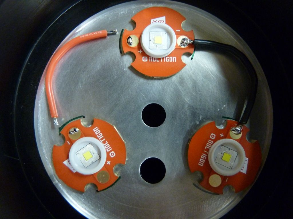
I've used AS5 religiously, but now I'm trying GC Extreme, based on specs/reviews. I like the way it applies, and maybe won't dry out as easy as AS5 does - again, not really sure here. I put the LED alignment pieces on the LED's and use the reflector to align them in position, trying to center the reflector as best as I can by hand. The green * on the reflector marks the LED opposite the wire hole. Probably not necessary, but I like to ensure the reflector match's up the LED's every time I use it to reference, and for the final assembly. also notice I mark the MCPCB position with the green marker as well:
The wires are bent into position, and solder in the outer half to allow for clearance of the reflector. This would not be necessary to do for SinkPAD's, because on SinkPAD's, the + and - pads are wider apart than Noctigons. I really should have used SinkPAD's for all Shocker mods:
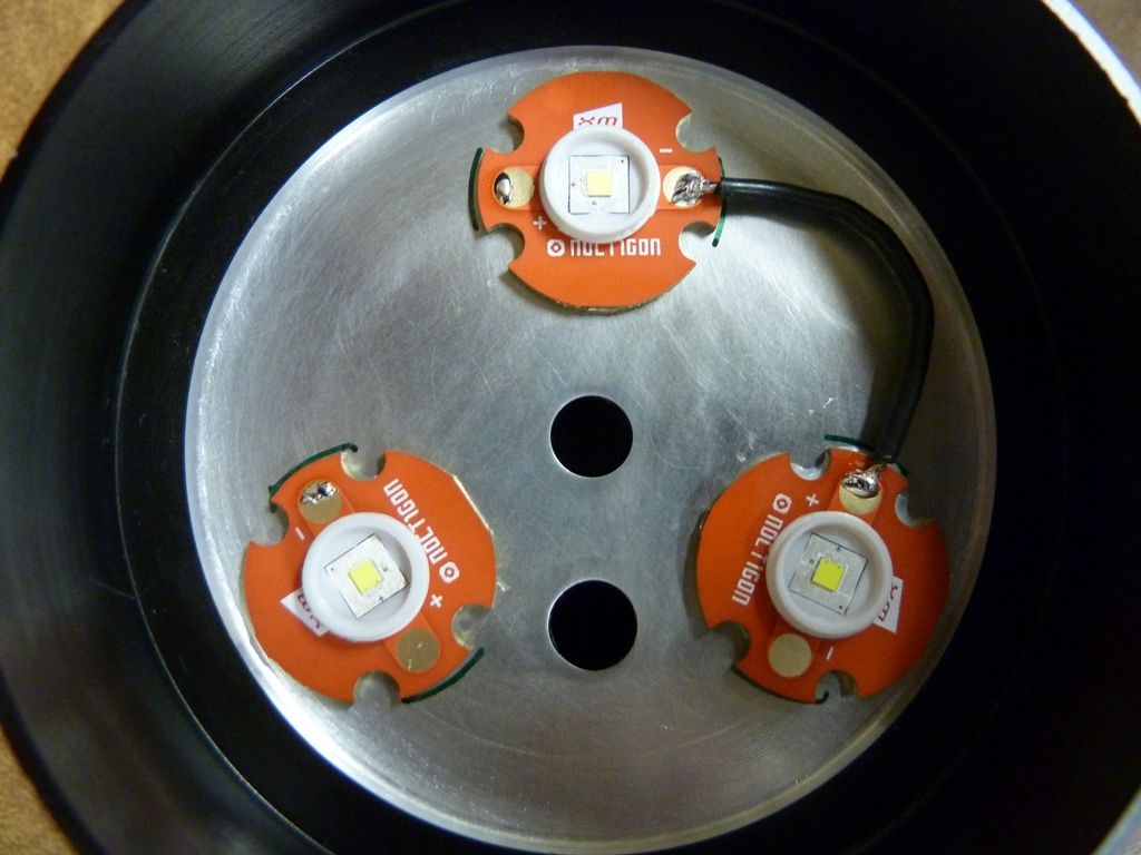
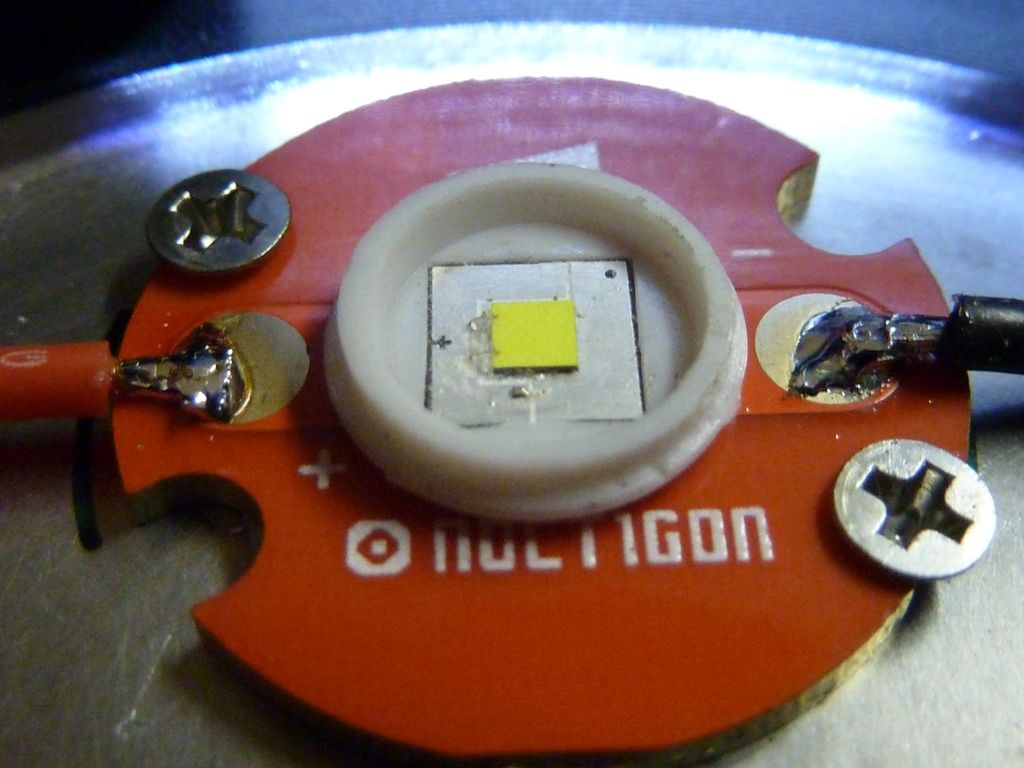
One MCPCB is secured by tapping mount holes. I started doing this on my last Shocker mod, and it's a great solution for a couple of problems. I much prefer using thermal grease rather than thermal epoxy under the MCPCB's. The problem has been the MCPCB's will twist when tightening the reflector down with the center screw, or specially tightening the bezel. Screwing down only one emitter guarantees the MCPCB's won't twist around, possibly causing the LED wires to be cut which creates a short, but also keeps the other 2 MCPCB's floating so you can precisely center position them in the reflector - best of both worlds! Detail view:
NOTE: The screw on the left is actually positioned outside the pill, so the hole I drilled punctured the outer body by a mm or so, and is noticeable. I'll probably patch the hole up, then attempt to touch it up with high heat paint. When I do this again, I'll turn the star so the screws are positioned equally from the edge, so they both will be within the body of the pill.
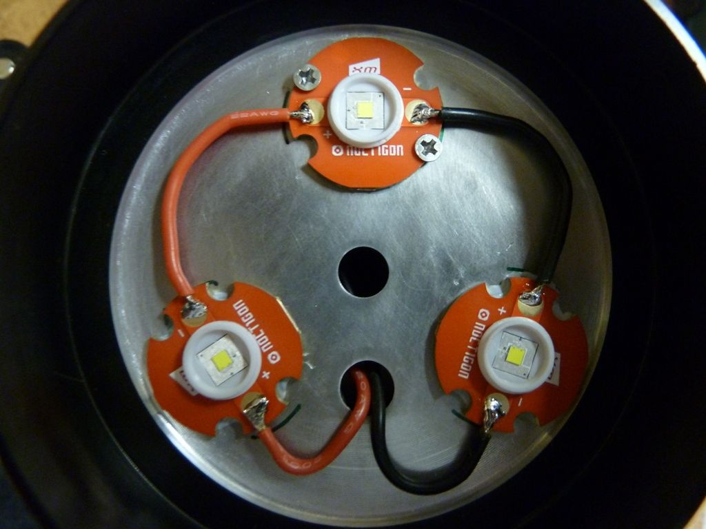
Final touch is kapton tape to prevent possible shorts with the soldered LED wire connections on the reflector. Hopefully it's not really needed, bu there just as a precaution. The dremeled out dips are sanded to smooth out the edges before the tape goes on:
Here's the driver mounting, with the retainer ring. These surfaces and the threads are coated with NO-OX-ID. When screwing down the ring, I hold one finger on the driver to prevent the driver from turning, which could twist the wires into a mess, and put pressure on the connections:
Here is my throw measurement setup. It's simple and crude, but seems to work well. The black sandpaper is there to suppress reflection:
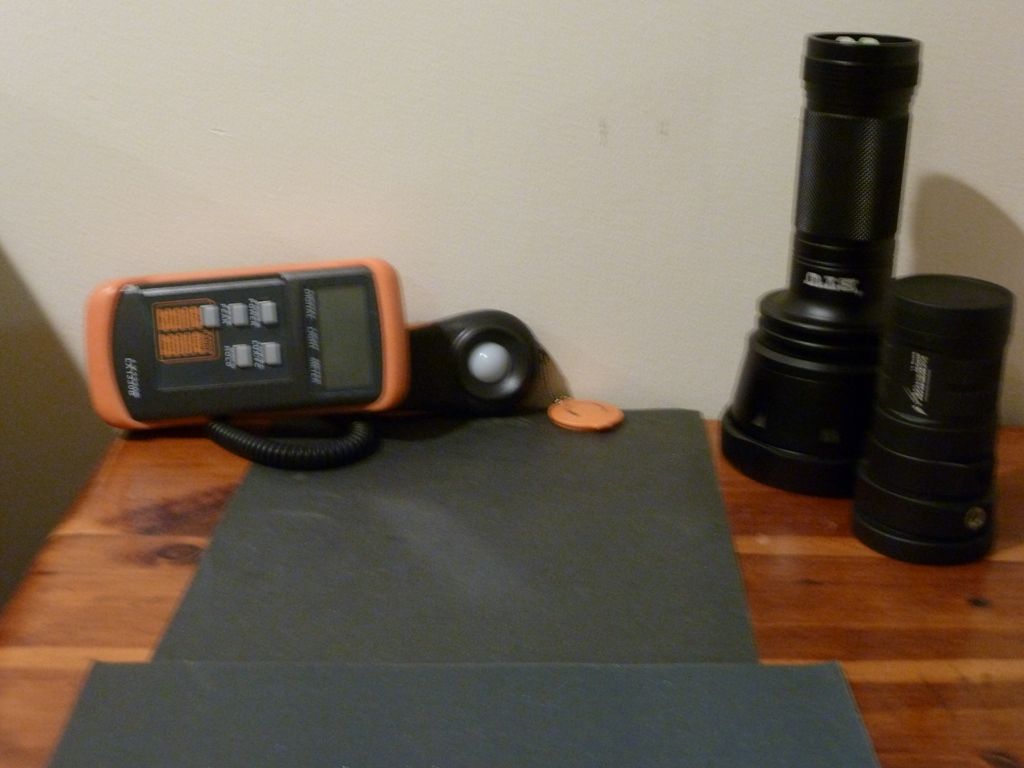
Here's the PVC lightbox. It's important to use dark colored foam. What's great about the foam is it can be cut to size, and you can created different size openings. It's white PVC that is painted black, and has glass epoxied in on each end, just inside. The right side is for mounting the light meter, while the left side is used to stand the flashlight on, so it actually sits on the glass that is under the foam:
Ok, that about wraps it up.
Results:
- with a set of freshly charged LG HE2 2500 mAh cells, measured 6.44Aacross the switch
- lumens: 4,964 at start - 4,726 at 30 secs(in my PVC lightbox)
- throw: 495 kcd measured at 5m
When measuring amps, I literally saw a 6 inch spark one time at one of the DMM leads by the switch!! The 6.44 amps is the highest I've gotten from any light or mod. It's not a measurement at the LED, but since it's a 3S cell to 3S LED effectively a direct drive, I'm thinking it's very close to what the LED's are getting.
For lumens and throw measurements, immediately following the Shocker measurements, I measured my stock NOVA MM15 light: 5,250 lumens at 30 secs, and 18 kcd. The factory ANSI specs for this light is 5,233 lumens and 19.6 kcd, so I think my measurements are in the ballpark. The variation in throw is not surprising, since LED alignment and reflector variances can effect this easily.
The lumens OTF measurement of 4,726 is the highest I've gotten from any of the dozen de-domed Super Shockers I've done.
For throw, this is the highest I've ever measured. There were brief times the throw exceeded 500 kcd (max'ed out at the 10X scale on the meter). I'm speculating the actual throw is higher than 500 kcd if measured at a longer distance, based on a de-domed Super Shocker rdrfronty measured, at 15m, compared to my measurements at 5m of the same exact light at the time.
Further Findings/Usage Notes:
With KeepPower 3400 cells, I measured about 4.5A across the switch, and for unprotected Samsung 28A's from a laptop pull, about 4.8A. So the results you get will be dramatically effected by the resistance of the cells. Also, you would expect the amps to drop pretty steadily as the cells deplete. If you want to go with protected, probably the best cell to use is the protected Panasonic PF's - Richard at MtnElectronics is one source. For unprotected, I really like the new hot 2500 cells, like the LG HE2's, Efest 35A's, SONY VTC5's, and Samsung 25R. All these cells have low resistance and longer runtimes, which really means longer times to run at higher amps, than say a 1600 mAh or 2000 mAh cell.
As with any extreme high amp light, the user has to be extremely cautious and use high quality cells. Even a Shocker will get hot quickly running 3 LED's at over 6A each, and using unprotected cells to full drain is very risky and dangerous.
I did make one major "oops" on this light. When I drilled the holes for tapping the screws for holding down the one MCPCB, I didn't realize one of the drill holes was outside the pill, so it did puncture out the side, in between the heat sink fins. If you look straight on from the side, you can notice it. It could probably be touched up with black high temp paint to hide it. I got some, so may give that a try...
06/10/2014 Updates:
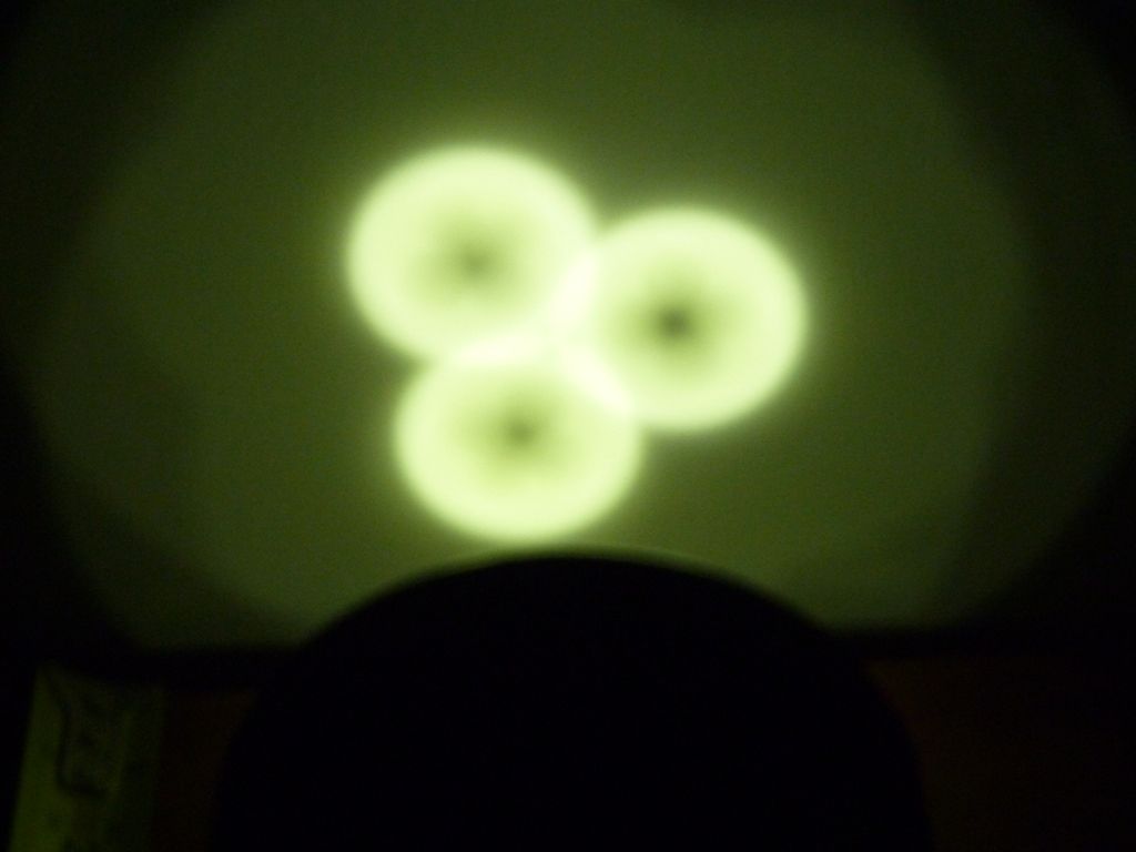
Here is a view of the beam on low mode at 4" from the wall. It shows the classic black holes in each beam:
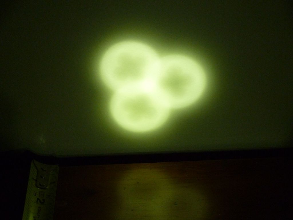
This is a view at 8" from the wall. Here you can see the black holes are pretty much gone. There's still some shading, but I don't consider that a black hole. This is very close to the wall for getting the black holes to disappear. Camera settings were kept the same (F6.3, 1/2000, ISO 400, WB: Daylight).
I did some comparative measurements of batteries and throw only:
- 3 new Samsung 25R's slightly over charged, 12.65v with no load. 6.83A across the switch w/load: 507 kcd
- 3 LG HE2's slightly over charged, 12.67v with no load. 6.80A across the switch w/load: 515 kcd
The 25R's dropped to 4.11v and 5.90A after the throw testing, maybe 1-2 mins of runtime. The HE2's dropped to 4.15v and 6.65A after the throw testing, maybe 1-2 mins of runtime as well. These are not precisely measured runtimes, but gives you an idea how much they drop.
 .
.