Look what I got in the mail today:
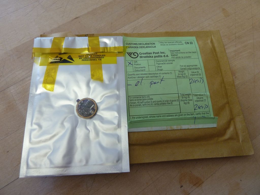
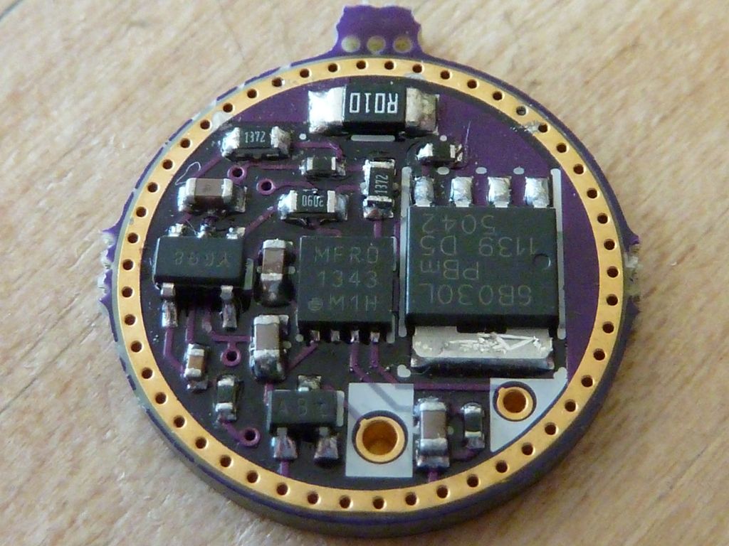
Oh wow - the fun will begin. The board has maybe a couple of solder splash's, not much, pretty clean. I'll clean it up with isopropyl alcohol a little first. No docs with the board, but he has everything covered in the driver thread OP: https://budgetlightforum.com/t/-/25225.
Not sure yet host - Maybe a Yezl Y3 with the tail and e-switch, or a Small Sun ZY-T11 e-switch type. I feel it's best served by an e-switch light, but certainly is designed to go both ways.
If anyone has any suggestions for test methods, I'll listen, but may not have the equipment or knowledge. HKJ will do his usual thorough driver test on this, so I'll look at mostly the usability and basic performance and functions.
Wed 07/23/2014:
This morning I was able to solder on some 20 AWG leads, add a temporay spring and test it on my simple bench setup. It works: all 4 std modes, etc. My bench setup is 1 XML/aluminum MCPCB with 22 AWG leads/clips, 1 XM-L2/Noctigon with 22 AWG leads/clips mounted on a large aluminum piece, and a simple one cell battery holder wired with 22 AWG wire leads/clips. Sorry no pics yet.
Results
Mode XML XM-L2
low-low 0.02A 0.02A
low 0.09A 0.09A
med 1.13A 1.13A
hi 3.48A 2.92A
Conclusions:
- I can't get to 5A, most likely due to the test fixture setup with all these long 22 AWG wires, alligator clips, poor qualty battery holder (expected)
- the lower amps on the XM-L2: expected because of all the voltage drops in the test fixture - XM-L2 on copper have a higher Vf demand
- what's really nice is the lower modes stayed dead-on consistent, and this is unusual I believe. I think a typical PWM driver would scale all modes, not just hi mode. This indicates why this driver is superior to PWM based drivers.
- In percent ratio of amps mapped to 5A as 100%, the modes are: 0.4%, 1.8%, and 22.6% which maps very closely to the LD-1 specs of: 0.3%, 1.5%, and 20%. Slightly higher, but not sure if his specs were in amps or output - perhaps led4power can explain
I did some debating on what to mount this in, and decided to do a HD2010 initially in a copper pill (simple power switch). I got a VOB copper pill all prep'ed already, so should go pretty fast. Plan is to move it on to a Yezl Y3 (power switch and e-switch), probably it's final resting place.
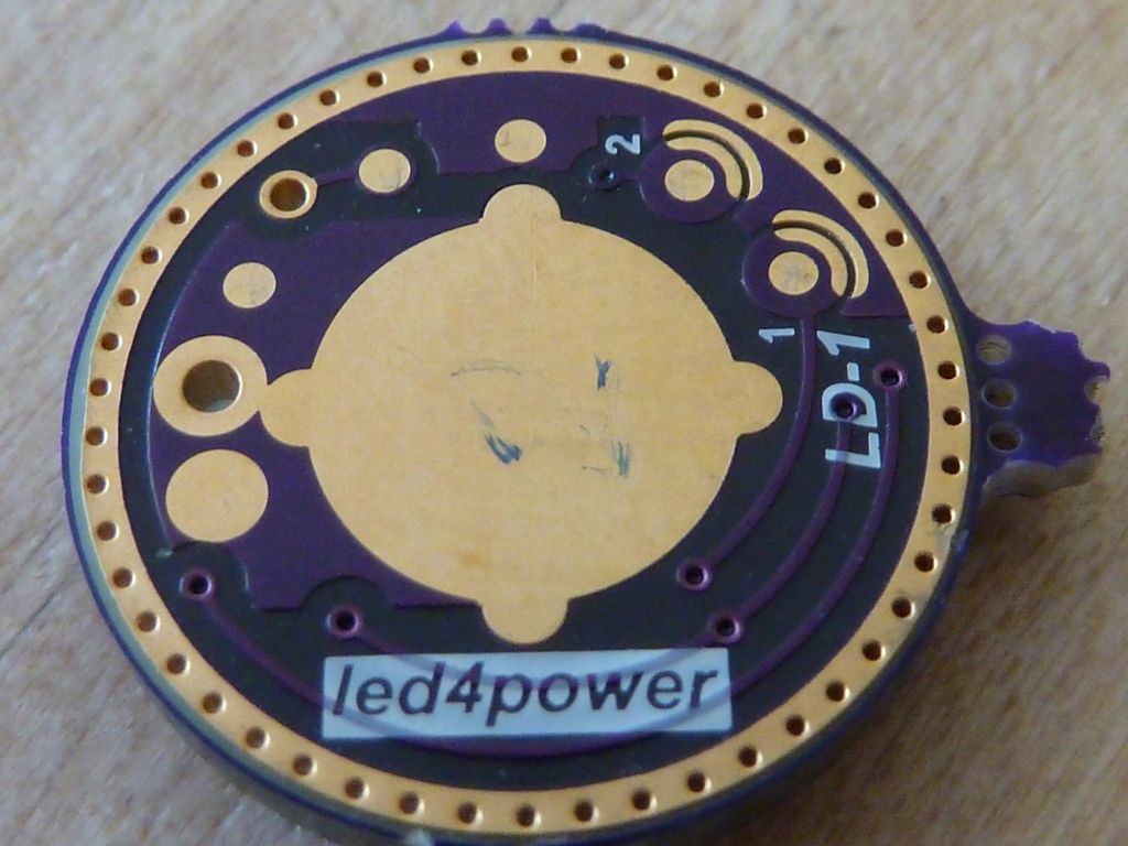
The LD-1 measures 17.18mm in diam, 1.63 mm in height using my digital caliper. A Nanjg is 16.90 x 1.55, and a BLF17DD is 17.01 x 1.57 mm. I found the LD-1 pops right in to a P60 pill and a stock Convoy C8 pill, but requires sanding down to fit any of the copper pill, or brass C8 pills I have. So, got the file going on the edge and got it down to bout 16.90 - 16.95, and now it's fits in real nice to the HD201 VOB copper pill, and all the others.
Thu 07/24/2014:
Got the board mounted in a HD2010, in a VOB copper pill. Tried a bunch of cells to check max amp readings using just the bare pill. Good news is I can hit 5.07A on several cells, but other cells can't quite make it. I have a XM-L2 U2 1A on Noctigon screwed down to the smoothly sanded pill top, using GC Extreme grease, 20 AWG LED wires. Also used the infamous "copper" spring from FastTech -- the spring does still add resistance, so added 22 AWG copper wired down the middle, and now I get higher amp readings: Powerizer went from 4.93A to 5.07A, so this proves those copper springs are not as good as copper wiring a spring yourself.
Cells Making 5.07A: Powerizer, LG HE2, Sam 25R, SONY VTC5
I'm only getting 4.84A on a fairly new EVVA 26650 unprotected (KK cell) at 4.20v from MtnElectronics, so that is sort of bad news not being able to get the full 5A. But, there may be some other variables going on because I'm getting some inconsistencies with these readings. I'm passing along my finding to led4power in pm's.
Sun 07/27/2014:
I applied the resistor change led4power recommended as a result of HKJ's testing. I decided to enable turbo mode via the moon #2 pad and see how it works.
The way turbo mode works is it replaces hi mode with what should be a DD mode. I ran some tests on a few cells, here's results. "Hi" is moon #2 OFF, "Turbo" is moon #2 ON:
Cell Hi Turbo
Powerizer 4.19v: 5.07A 5.29A
LG HE2 #2 4.21v 5.07A 5.35A
SONY VTC5 4.18v 5.07A 5.14A
These are the identical cells, so I'm pretty confident these #'s reflect the differences. However, there are lots of fluctuations between cells. I think what these results show is if you want a turbo mode for a single XM-L2/copper configuration, this driver appears to not be able to produce as much amps as the BLFDD17 driver for example, which can do higher with comparable wiring, LED, etc. I would suspect the FET comfy chose for the TINY13A based FET drivers has lower resistance. Also even being able to get to 5A may be a challenge for most cells in a single XM-L2 or XP-G2 on copper configuration.
Current Controlled medium mode vs. a PWM medium mode
To compare to a Nanjg PWM based driver, I measured the LD-1 in medium mode at 1.13A against a medium mode in a 12x350 7135 PWM driver in the same flashlight (HD2010).
LD-1 turbo mode configured, medium mode 1.13A, lumens: 483 @start, 479 @30secs
Nanjg 4.2A driver (measured 4.34A @tail), medium mode: 1.32A, lumens: 381 @start, 371 @30secs
*** the LD-1 is 29% brighter, even though it is running on 14% less power. I'd say this proves how really poor PWM modes are on a higher powered light, and how efficient true current controlled regulation is.
Current Controlled medium mode vs. a PWM low mode
LD-1 turbo mode configured, low mode 0.09A, lumens: 34
Nanjg 4.2A driver (measured 4.34A @tail), low mode: 0.16A, lumens: 44
The LD-1 is using 44% less power, and produces 23% less brightness.
I'm not sure why these results are closer, compared to medium mode. Might be some non-linear scaling, plus the fact the medium modes were much closer in amps.
Tue 07/29/2014:
For some reason, I thought the LD-1 was set for non-turbo, but the amps reading is above 5A, so thinking clearing the solder on the moon#2 pad did not work, though I did test for continuity. Anyway, I wanted to do a test similar to HKJ's test for brightness % (https://budgetlightforum.com/t/-/27995), but for mine, I'll use lumens in the PVC lightbox. I decided to use a slightly depleted LG HE2 that records a clean 5A at the tail. I realize HKJ's amps are measured at the LED, so may not be the same.
Here's the results in the HD2010 (copper pill, XM-L2 U2 1A/Noctigon, 20 AWG):
Amps (HKJ) Lumens OTF % of max HKJ % of max
5.0A (5.0A) 1,544 100% 100%
1.13A (1.1A) 466 30% 32.4%
0.09A (0.083A) 37 2.4% 2.64%
0.02A (0.022A) 21 0.45% 0.57%
These #'s are dang close! Might be our measurements for the "high" mode are not quite compatible - not sure how he measured output, but I'm pretty confident in the consistency of ranges of low to very high readings in my PVC lightbox (my high may be higher?). Or could be simply tolerances. May not matter much, but the scaling is very consistent.
Sun 08/02/2014:
I have the LD-1 installed in a fully assembled, upgraded Yezl Y3 (with e-switch). Further details can be found here: BLF - Yezl Y3 Picture Breakdown. Here's a pic of the driver:
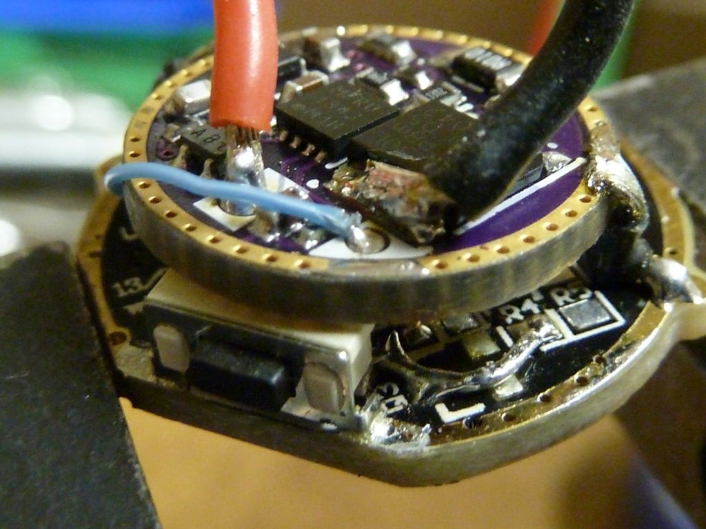
It's still in turbo mode - can't seem to get it back to non-turbo. Main reason of using the Y3 is to have a decent host than can take the high amps, and so I can test the more advanced functionality of the firmware (multi-mode sets) that are only available with an e-switch.
The piggyback mounting went pretty well. It's a nice low profile driver. As you can see above, I stripped off all components from the old driver and traced the switch to an MCU pad, and routed a wire (the blue one) from the MCU pad on the old driver to the e-switch pad on the LD-1.
Some Measurements:
LG HE2 @4.18v 5.46A
KK 26700 @4.21v 5.32A
On the KK 26700, lumens: 1,513 @start, 1,452 @30 secs (1,454 OTF), throw read @5 m: 111 kcd
Modes and Mode Switching
The tail switch and e-switch work pretty good together. Using the first (default) mode set, you can easily change modes via either switch, and of course the e-switch can turn the light ON and OFF as well - nice combo. I did notice the e-switch delays mode changing, thinking this is on account of supporting a double-click. It feels a little unresponsive to a single click as a result compared to other drivers.
In attempting to test the other mode sets, I'm kind of stuck. Thought I had it working in ramping, but could not figure it out - seems like there are delays, and in attempting to figure it out -- I'm stuck now - can't change mode sets, and not sure what exactly mode set I'm on now. It's acting as a two mode light now, with both modes pretty low, but close.
Update: Fixed the problem! I probably overrode the temp threshold setting, so the light was thinking it was constantly over-temperature. I got a much better feel for ramping mode now. It works great in the lower 50% range, but in the upper half it's very hard to notice the ramping at all - I'm sure that's because in output %, it doesn't change that much, as compared to the lower 50%.
Ramping is basically a single mode, but allows you to get the single mode to any level of brightness you want. I did notice that if you ramp it down to the lowest setting and use that, when you turn the light back on, it very briefly flashes a higher level of brightness. I reported this to led4power.