I bought one a bit ago because it looked interesting. And it is. A micro boyscout/milspec style light with fantastic throw and works off CR123s, so potentially good for muggle gifting.
Except for the fact that it draws 2 amps off a CR123. Cripping draw for that cell normally. So the light is insanely bright though, right? Wrong! Its a dim light, the same brightness as a 2AA Ultrafire C3. That can’t be right…can it?
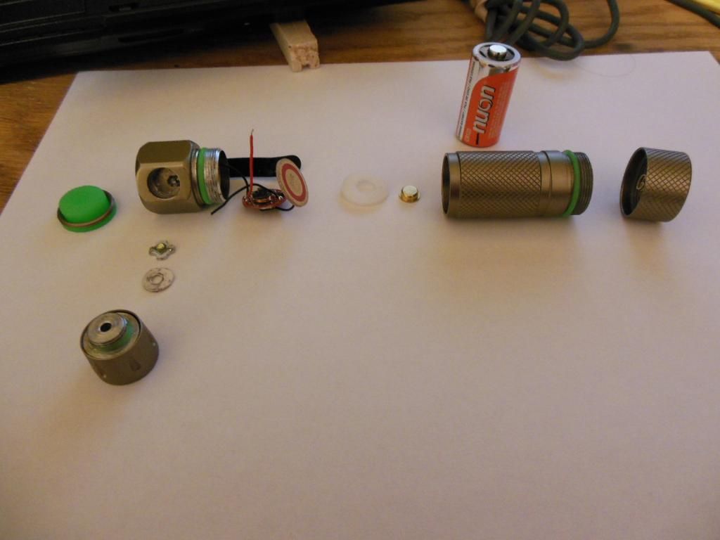
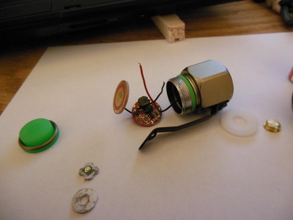
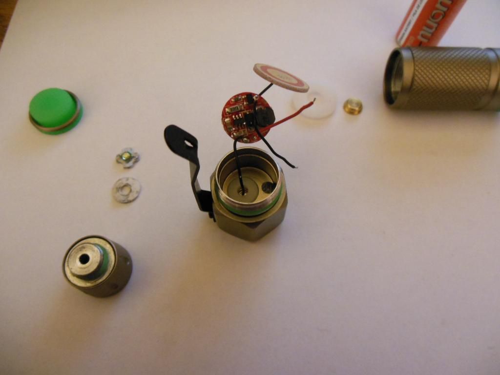
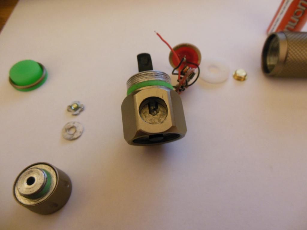
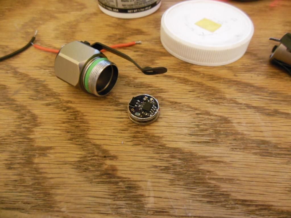
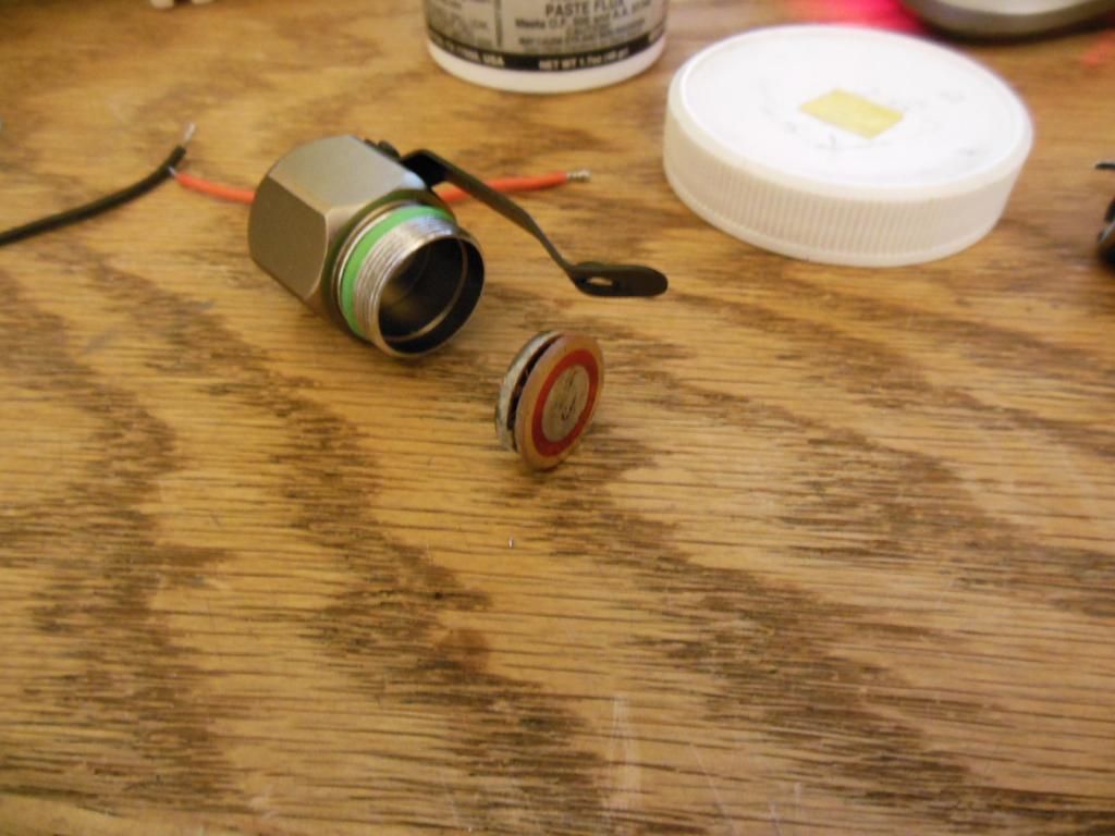
Here’s what the light looks like disassembled and gutted.
I linked my DMM in series with the XP-E emitter and saw…500mA
This driver takes 6 watts…and turns it into 1.5ish watts. 25–30 efficiency.
Wow
I actually have no idea why it would be that piggishly awful. Nothing looks terribly wrong with it, but its horrible. Maybe the red-PCB trustfire drivers are just crap? [remembering the Trustfire X9 review on this site]
So first off, I’m binning the stock driver. The contact board is staying as 16mm is kind of a unique size, but methinks the BLF SK-68 7135 driver is going in there [with only 3 or 4 chips]. The biggest issue is the emitter. That star is tiny and rightly so, the hole is just barely short of 9mm in diameter. I’d have to hack alot of material off the Noctigon that XP-E2’s come flowed on from mtnelectronics.
And a copper star is kinda a good idea for any meaningful power because there’s a bit of a hole directly under the emitter where the body is carved away for the emitter wires.
So I’ll keep this thread updated as I make progress but I’ve spent waayyy too much on flashlight stuff the last couple weeks, going to wait until next week to buy the bits for this little project.
I gave up on modding the Z2 (the AA sister of the Z1) a year ago because a) I could not get the switch out (you already went past that point!), b) a thicker led-pcb would prevent screwing in the reflector, that in the stock situation already hangs on a tiny bit of threading, c) the tiny and hollow bit that the led-pcb sits on is anodised, and it is a pain removing that inside the hole, d) it needs a better driver and there was not a decent 15mm one at the time.
How are you going to solve that the battery minus must go via the switch to the driver, in other words, insulate the driver from the shelf?
Z1’s still one of our favorite ‘pedestrian crossing’ lights — hi/low/strobe with mode memory.
I’d love to see progress on improving these. I killed the one I tried to take apart and passed it on to another modder.
I didn’t touch the switch, I just put the tip of the soldering iron in the hole, pressed it where I saw solder, and tugged the wire out. I’m going to leave the last 5-6mm of the new wire bare, heavily tin it, and apply heat to the bit of wire left outside the ‘port’. I have a rough idea of how to get the switch out, but I’m not going to bother unless I ruin it. The bore of the driver cavity is anodized, that will insulate the BLF SK68 1735 driver for me. As for the thicker LED mcpcb, mine screws in all the way, so a thicker pad might be workable. If not, I’m only putting an amp through the emitter so re-using the original star won’t be a big problem.
I think these work OK if you don’t use high mode much. They have unusual advantages for this price class, so I am listening to what you find. From the pictures, the simplest mod. would be just to discard the driver and use one mode direct drive. I have a CR123 light with no driver, and it works nicely. Heat dissipation may not be much of an issue with CR123a. It could be with lithium ion.
I received some XTAR 16340’s in the mail from Richard at mtn. One of them made my Opus throw a hissy fit trying to discharge it at 500mA and out of curiosity I tossed it in the second Z1 I’d bought for gifting.
950mA. And this Z1 I also tested with a CR123 and it too drew 2 amps. But then CR123s have a fairly abhorrent voltage drop when tasked with anything beyond powering a rice-grain LED. But the driver is still taking 3.5W in and hacking it down to 1.5W out. Still 43% efficient, still atrocious. But the drivers work. Not very well, but they work. I winder if I shouldn’t replace the laughably thin stock wires with 22ga and see if that doesn’t make things cook a bit better. Maybe TF used better wires in the lab when designing the light. Who knows.
Protected 16340’s do work in this light at least, so a 7135 driver is a go. Well, it was a go in the first place even assuming a need for unprotected Efest cells as the intended replacement uses a 105c MCU. But I digress…
*
[EDIT]* I did some futzing around before work and tried using 22ga wire for everything. Ended-up cutting power to the emitter in half and somehow the driver doesn’t want to do low-mode or strobe anymore. XD Soooo yeah, Tuesday after the Check clears Richard’s getting another order from me.
from experience, the Z1 head works fine on the Z2 body allowing easy use of alkaline or NiMH as well as li-ion.
It’s still plenty bright run from an Eneloop. I much prefer the Z1 (mode memory, lo-hi-strobe) to the Z2 (next mode memory, five modes) for use, routinely, as a pedestrian in crosswalks. It wakes drivers up.
Starting off with 3x380 chips. That’s about all an aluminium-sunk XP-E can handle anyway. Using the original contact board, simply solder-blobbed the + pole on the BLF SK68 driver.