So, I went to my local Tractor Supply the other day, looking to spend some money on a flashlight, because Chinese holiday has two flashlights of mine held up in shipping, and the BLF Edition X6 groupbuy is waiting on approval of yet another sample before it will go into production. So, I get there and start looking at the selection. Well, they have a nice little selection of CREE LED flashlights. All of the JOBSMART brand flashlights tell you what LED is featured and they have FL1 ratings for lumens, throw, and runtime! A few of them are XP-G2 R5, one or two of them are XML T6, and a couple feature XM-L2 T6 LEDs. You can right now get a 3D silver JOBSMART flashlight with XM-L2 T6 LED rated at an FL1 650 lumens for about $30 at my local Tractor Supply. But, alas, that is not what I got. What I got was this:
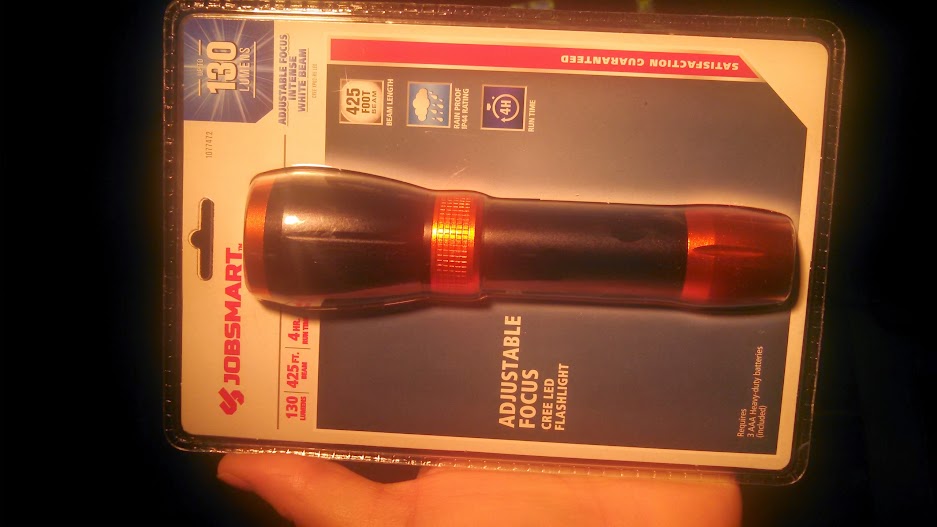
I paid $9.99USD plus tax for this thing. It’s basically a zoomie, it runs off of 3X AAA in a carrier, and uses a CREE XP-G2 R5 LED for a claimed “up to 130 lumens” FL1 rated output.
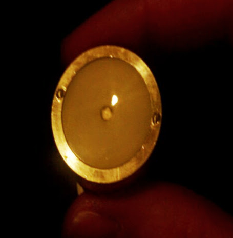
I took a few pics of it in the package, then started pulling it apart. Oh wait, no, before I pulled it apart, I looked at the front of the lens, and noticed that when I zoomed out (pulled back) the LED looked centered, but when I zoomed in (pulled out) the LED was off center. Hmm, that’s weird. Okay, on second thought, how about a test before cracking it open? Well, it was a bit disappointing. It has a zoom range of not-quite-spot to just-shy-of-flood. I didn’t actually take any beam-shots until after putting it back together, but, here, see what I mean:

Okay, so what we’re seeing here is a quick comparison shot I did in my basement. The subject wall was about 7 feet away or so. In my hand were the JOBSMART zoomie, and my Olight S20 Baton. The JOBSMART light was zoomed as tight as I could get it. It was the spot on the left. So, my S20, with a small smooth reflector has a much smaller bright spot than this zoomie fully zoomed. By the way, the zoomie was on its maximum level (It has Hi, Low, Strobe) and the S20 was on Med, rated for 120lm when using 2X CR123A cells, but I was using 1X 18650, so it was a little lower. Some of you will notice that the Olight has a nicer tent as well, although a beam-shot on a terracotta block wall using a cell-phone camera isn’t going to show the true colors.
Finally now, we can talk about the break-down. I took the head off, and saw immediately why the LED looked off-center when I viewed it down-the-barrel earlier:
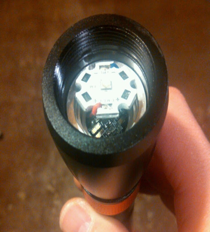
Yep, it was like that when I opened it! Here we have a CREE XP-G2 LED on a 20mm aluminum star, hanging out from the hollow aluminum pill that it is supposed to be resting on. There isn’t any kind of adhesive or epoxy or screws or anything at all to hold it down. And here’s what it looks like, when I’ve been able to get it to stay down long enough to take a picture:
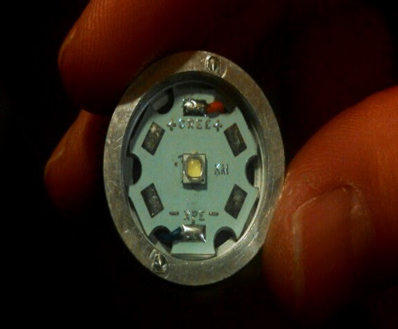
Yikes! Not much contact there! And, I think the centering ring is what is supposed to hold it down, actually, so here are a couple of shots of that marvel of engineering:

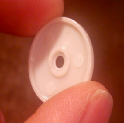
Here it is installed. Sorry for the dark picture.
Well, let’s move on. We might as well look at the complete pill:
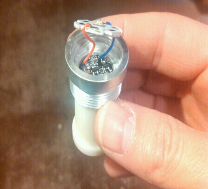
Okay, there’s the top, with the star hanging out on some very thin wires! What is that plastic thing dangling from the bottom? Why, it’s the battery contact, of course! See:

Well, it’s not very impressive inside, either:

A long spring soldered to the underside of the driver makes the journey to the battery complete. At least they put a brass cap in as the actual battery contact. ![]()
Now, let’s get to the zoomie parts. Here you see the head of the flashlight is actually quite thick and appears to be well made. However, as we all know, the heat is generated in the emitter and driver located within the thin body, which doesn’t give much help to heat dissipation.


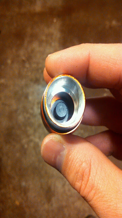
You may be able to see it in these pics, if you’re really experienced with zoomies. But, I found the reason why mine won’t zoom in or out much. The travel is very short and the lens is very close to the LED even when zoomed. See the bezel? It screws into the head, and it holds the lens down on a small shelf just past the threads. At least we got double O-rings!
Finally, here we are at the other end of the flashlight, the tail-cap. I haven’t yet attempted to take this apart, but here’s what it looks like:

Well, I looked it over, then I put it back together and looked at the output again. That’s when I took the beam shots. I tried de-doming the LED to get a little smaller spot. I didn’t notice a difference. I’m so unimpressed, I even took a couple shots comparing it to a little cheap AA zoomie I had nearby. Here it is:

And, here are the shots, on an old refrigerator that also resides in my basement:


Those were taken at 4ft away from the fridge, with my phone’s camera. The square spot on the right was the little zoomie. Both are max zoom. The small square was too much for my camera to handle. It actually appears about 20 percent smaller to the naked eye. I de-domed one of these cheapies and got a laser beam! This one was running on a 14500, in case that matters to anyone. Speaking of disclaimers, I guess I should say that none of the pictures in my thread were taken at the same settings, for two reasons. One is that my phone does a lot of automatic stuff that I can’t control. The other reason is that I made some adjustments to the exposure level on most shots in order to get the camera to see as close to what I saw as possible. Essentially, I tried to make the pictures contained in this thread as accurate to real life as possible within my limitations.
My conclusion is that this light could have been better engineered. I like the style, although the orange color is not really my taste. The zoomie head should have had more travel in order to zoom into a tighter beam. The LED star should have been secured down some way. I haven’t looked at the driver yet, or the guts of the tail-cap switch. I will update as I get to those later. But, the wires connecting the emitter were super thin. I’ll try to get an actual wire gauge if I can, but I’m guessing 24 or 26. The pill is not just hoolow, but very hollow. In other words, the walls of the pill are thin, and the 20mm star barely makes contact with the thin shelf provided on the inside of the pill. The long spring is made of thin wire, and not copper, so I’m sure it adds tons of resistance. With a little better design (and implementing said design) this could have been a great zoomie. The body is obviously long enough and wide enough to accommodate an 18650 or better. I’ve not measured it yet, but it might take three 18350’s if the driver spring were shortened. The pill area is also long enough to accommodate a solid core pill (there is at least 1/2 inch space between the driver board and emitter star). And the bezel could be bored out to take the lens from the front, pushing it further from the LED, which in turn would give it a tighter spot and longer throw.
I may in the near future do a mod major overhaul on this thing. That’s partly why I’m talking about it now. I want to like it, but it needs lots of help. I wonder why this wasn’t better designed from the beginning. But it may yet offer a nice canvas for my creative interpretation of what it could’ve been. Let me know what you think. Also, if there is anything I missed, let me know and I’ll add it when I do the update(s) with stuff about the driver, the tail-cap, and some basic measurements.
Update #1: I took a closer look at the driver, and took apart the tail-cap to see what the switch looks like. So, here’s a look at the stock driver.
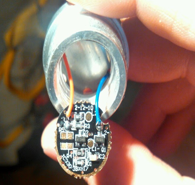
Well, being the newbie that I am, I have no idea what that is all about. If anyone can enlighten me, that would be great. Here’s what I can make out: The board has extra L2+ and L1- solder pads as well as R4 and R5 pads not being used. I wonder if those would allow any significant changes to be made. It’s hard to read in the picture, but the resistors at the top are R2 and R3 and are both labeled 1R0. Near the bottom is R1, labeled 472, as well as D1, labeled 000. Q1 on the right is marked 8233 and Q2, in the middle, is marked A1SHB. There is also a C2 onboard, and the LED wires are soldered onto L0+ and L2- pads. I didn’t get a picture of the back of the driver, but it is clear except for the usual battery connections: Batt- is a ring around the outside and Batt+ is a large pad in the center with the unusually long spring soldered to it.
After that, I took the tailcap apart:

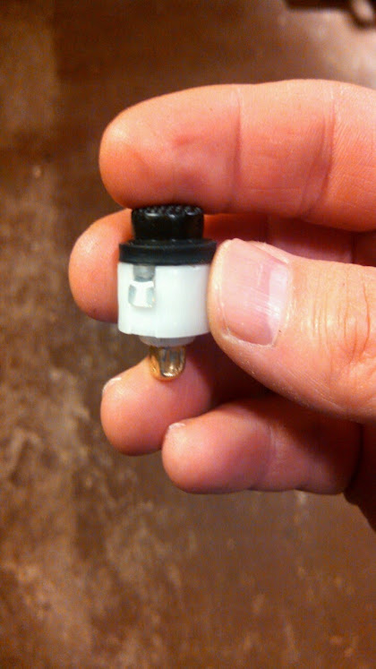


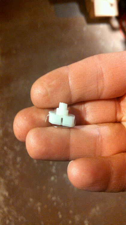
What we’re looking at here is a strange extension that was set up inside the tailcap. There is a metal post which extends out the back of the tailcap as the button to be pushed. It rests against a rubber boot which rests atop the clicky switch. The switch is inclosed in a round spacer which contains the spring and battery post for the negative side connection. You can see in the pictures that the battery post is pretty rough looking and basically a square shape. That’s because the only way I could get any of the switch mechanism out of the tailcap was to pull on the battery post with my pliers, and the post, being hollow, got squeezed in. However, after putting it all back together, it still works (as well as it did before, anyway).
So, they made the host a lot longer than was needed, I suppose so they could get the look they were after. They made up for the extra length on the inside with some extensions front and back of the battery carrier. I still don’t have a caliper to take any measurements, so I’ll have to update again if/when I get those measurements. But just looking at it, if heat weren’t an issue (heat dissipation in this thing has got to be awful) I believe that up to three 18350’s could be made to fit inside by shortening the spring on the positive side and possibly boring out the tailcap so the switch can be pushed deeper into it, if need be. The star is 20mm, so it could be traded out for a DTP with a much more powerful emitter. The bezel would take some modification to move the lens out further from the LED for better focus. Or better yet, put a TIR in and do away with the zoomie function. Then somehow make the nice thick head part of the heatsinking. I don’t know about the driver, but it would probably have to be heavily modded or else replaced. The pill could be replaced with a solid copper or aluminum pill. It sounds like this light would take more work than it’s really worth, but like I said before, I want to like this light. I like how it looks and I already bought it anyway, so I would like to make it useful, if I can. If I do mod this light, I’ll be sure to start a build thread so you can see all the wonderful newbie mistakes I make! :party:
