Using 20mm non-direct thermal path copper emitter bases.
Replacing press fit aluminum pills with copper.
Replaced MCU with Attiny13a loaded with JonnyC STAR Momentary FW, modded by Tom E for a Strobe Mode and by me to turn on certain built-in features and add more modes.
Increased current to 3 amps per emitter by decreasing resistance on the Voltage Sense Resister Bank.
Changed from 2S2P battery pack to 3S in order to have more voltage overhead for 2S XM-L2 emitters.
Built slimmer battery pack for headlamp usage (Not yet done).
Steps performed so far:
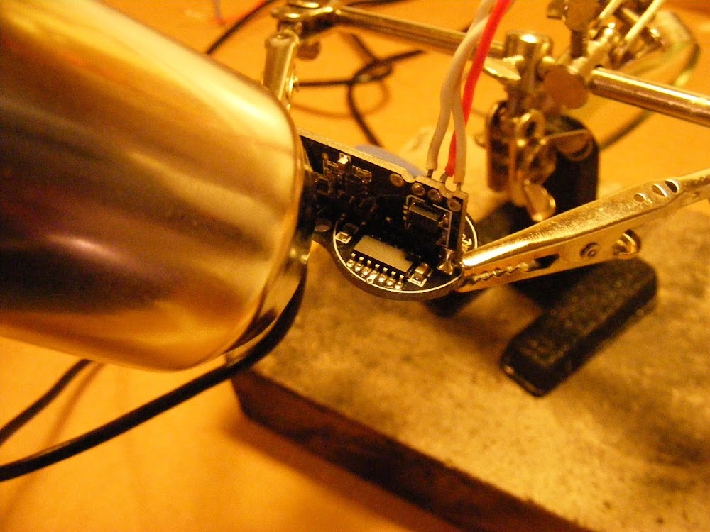
Increased current with voltage sense resistor mod. This light is very light weight. So only shooting for 3 amps per emitter with 90 turbo timeout. Procedure is pull out driver with 2 screws and solder in a R33 (.33 ohms, standing up perpendicular and between the two R200's voltage sense resistors in the below picture). Increases current to each emitter (2S wiring with stock XM-L's and stock MCU) as follows:
Low .53 - .54 amps
Med 1.41 - 1.42 amps
High 3.10 - 3.11 amps
NOTE: MCU swap brought down emitter current to 2.67 amps. Added a R500 (in addition to the stock and R33 Resistors). Resultant current to the emitter is now as follows (Don't know what the stock PWM's were):
PWM
Emitter Current
(Modded)
Modded 2S Cells
Modded 3S Cells
1
0.01
.02
3
0.02
.03
9
0.03
.08
27
0.12
.33
81
.56
1.01
140
1.22
1.84
255
2.43
3.14
NOTE2. Member neons97 reported a voltage drop measurement of of .25 on the voltage sensor bank. Good info to know. This is consistent with the current measurements/resistance I have seen in this light. Thank you neons97 for reporting that measurement.
"Tailcap" or input current with 3S is a nice gentle 2.02 amps on the Highest Mode (modded). So efficiency seems decent.
MCU swap:
Unsolder stock MCU
Be careful. One of the heavy diodes slid off one of its pads during the process. Should have shielded with a piece of aluminum foil.
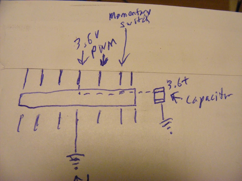
Connected power and probe to find pins used for Power, Ground, PWM out, and Momentary Switch. Here is a sketch made during the process. The pins for the indicator LED's appear to be the 2nd, 5th, and 6th pins on the bottom starting from the left (side with no capacitor). I will not be connecting them as the FW as it currently stands will not be able to control them. Even if it could, I probably wouldn't as I found them quite distracting.
Here is a pinout image of the Attiny13a with a link to it's source. The Momentary Switch connects to PB3 for the FW I'll be using.
Program Attiny13A with JonnyC's STAR Momentary modified by Tom E for strobe. Great FW. Can go up with fast click, down with slightly less fast click, strobe from anywhere with long click. So can go to low, high, or strobe from off. Can go to low or high from strobe. Awesome stuff. Modded for 7 modes, 1, 3, 9, 27, 81, 140, 255. LVP and Turbo Timeout features turned on.
Decided to reflow some pins directly to the driver board. Bent the ones that wouldn't be reflowed to a pad up. Pins 7 (PB2) and 8 (Vcc) will be shorted to each other as no voltage divider circuit was located and I didn't want to build on at this point.
Reflow of new MCU and air wiring of Ground and Momentary Switch Pins. Sorry, bad lighting conditions, substandard camera and no real photographing skills. Here is the Momentary Switch wire being pre-installed before Attiny13a is reflowed to board. There is a through hole to the switch.
Attiny13a reflowed (only 2 pins, Power and PWM). Also Ground Pin air wired to through hole.
Soldered wire that was pre-installed for the Momentary Switch. Sorry, really hard to see in picture.
Testing using a MT-G2 and a couple laptop pulls. Tape, rubber bands, whatever it takes to see if it just works. It did! Yay!. More great news. The driver is quite happy running on 3S cells! Current to the emitter was exactly the same as with 2S cells. Nothing overheated on the driver. Voltage Sense Resistors, the Large Diodes, and the Inductor got up to around 140F with the driver hanging in the air.
Due to internal thermal bottleneck, replace aluminum pill and aluminum emitter base with copper.
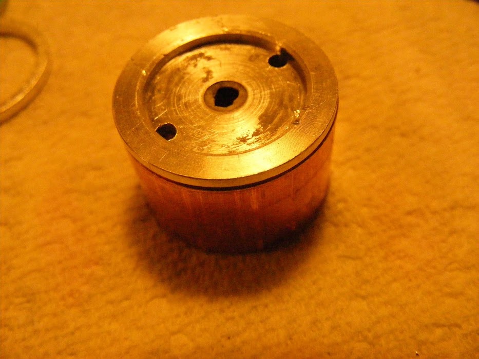
Luckily, the press in stock pill is the same diameter as a 3/4" copper pipe.
I need a little less then .535" if I want the copper pipe to reach all the way up to the reflector flange. Use a plumbing pipe cutter to make true cut.
Rough sand off the burrs and test fit. The bottom of the pill has not yet been made. Will use cheap indirect 20mm copper bases.
Ready to press in. Always round leading edges before pressing.
Pressed in front view. Took some persuasion to get in. Over time, the pressure will cause it to form to the irregularities of the casing. Well transfer heat well and will not be going anywhere.
Rear view
Bottom of pill is .071" thick copper sheet. (made from used copper pipe). Didn't go crazy lapping it as it will be reflowed to the copper bases (Not DTP) and only 3 amps will be pushed through each emitter.:
Reflowed emitter bases and back of "pill".
Back side. Just ran short wire from one emitter to the other instead of routing back to the driver.
Selected two XM-L2 T5 5B1 emitters for warmer tint and better CRI. For some reason I only get 2.67 amps to the emitters now. Guessing it's due to the new MCU as the emitters shouldn't matter running 2S in a buck driver with 3S cells.
Tested for thermal sag and it looks good. There is still some sag but is gradual and is when the exterior body starts getting heat saturated. Sag reached around 10% at some point over 200F (Sorry, didn't take good notes). In moving air (such as on a bike), there should be no thermal sag at 3 amps. At PWM 140 (1.84 amps) the temp of the body increases very, very slowly after reaching ___F.. Too slow to measure last night.
# of Seconds on High (3.1 amps)
Temp (F)
90
125
180
160
270
195
?
Stopped when 240F was hit
Copper taped back of "pill" with scraps from other projects and potted hot parts of driver. Neither of these things were necessary, but they are easy and cheap. Driver is not well connected to the body thermally and has no grounding ring or electrical connection to the body.
Beam Shots:
The first 3 modes are not visible on camera. Here are the 4th through 7th modes (PWM 27, 81, 140, 255), respectively:
Here is the stock light on High mode. Sorry angle and location are off.
Remaining step:
Develop battery pack solution that is comfortable for headlamp usage
Concluding Comments:
Pretty sweet light before mod. Better now, but I need to get rid of the whining on the 5th and 6th modes. Luckily, the 4th mode is more than enough light for me for most situations and high only draws 2 amps from the cells.
A gentleman from MTBR has contacted me asking for identification of the voltage sense resistor on his driver.
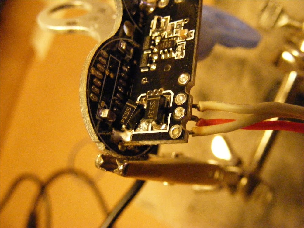
Sir, I believe that you have a bay for one resistor. It is the bottom right component in the first picture below that is marked "R010". I'm posting it here because I am a novice at electronics. I'm certain of my answer but I want others who know much more than me to have a chance to advise in case I am wrong.
Great mod ImA! I've been tempted to pickup one of these cheap head only units to play with TIRs in it, but so many of them are junk (drivers, heatsinking) and I didn't want to get extensive with it.
Thanks guys. Appreciate the nice comments. I have to thank that gentleman from MTBR for helping light a fire under my butt on this light. It probably would have sat a good deal longer. He has joined our forum and hopefully we will hear from him as he works on modding his light.
dthrckt,
The height of the basic light without the mounting mechanism is 1". The thickness of the handlebar mount is .3" at the peak of the arch. If I understand you correctly, 1" is the minimum clearance you need if you do not use a rubber pad or something. See pic below for a visual. Hope that answers your question on height as I'm not sure I picture your application correctly in my mind.
Regarding the $15 units. I would assume they will be the ones that don't have pills, just an aluminum mcpcb that rests on a narrow ledge. I don't know about the driver. There appears to be quite a bit of variation on the drivers in these. The good news, if it is similar to mine, is that it can take a 12 volt (automotive type) system. Been running mine on 3S cells today and it seems happy. It seems that drivers that have the same buck converter that is used in this light can take 4S. At least in 2 of the drivers I have tried it on. I expect this driver would be fine with it too.
Hope that helps. Let me know if you need any additional info.
So about the gentleman from MTBR… I think that would be me Hello everybody and thank you ImA4Wheelr for your great help and great effort. I will be posting about my modding progress as soon as there is any
the light (with no base) should fit between the railing and deck with ~ 1/8” to spare.
Interesting about the driver. If it always starts in high mode, it would be cost effective to use it. But, I’ll be using a separate switch panel to turn it on and off, not the switch on the light, so I guess I’d have to short that switch out. I’m not worried about the shelf, I figure I’ll have someone turn a couple slugs from copper rod (or hone the interior of the light if it is close enough to standard rod diameter).
anyway, i’m looking forward to your final product. That should be quite a headlamp!
Thank you for introducing yourself. I was getting tired of calling you a gentleman.
It's great to have you here. We only have a handful of avid bikers that I know of. They are probably fellow MTBR members for you.
dthrckt,
No doubt you can easily fix any thermal issues. You were more active when I first started and I remember admiring and being inspired by your projects.
The switch is momentary. So you can't just short it. You could, however, short the PWM pad to the 3.6 volt pad to its left. I would remove the MCU so that battery voltage indicator lights don't illuminate. They are very bright and will distract you (hurt night vision some too) on your boat.
Reflowed the emitters and wired this morning. Gets up to about 230F in 2 to 3 minutes on high (2.7 amps/ emitter). Stabilizes at about 185F at PWM 140 (which is about 1.7 amps per emitter). Both sitting measurements in ambient room temp with no air flow. Thinking about increasing the current some.
I checked the voltage drop over my DMM when it was reporting 2.7 amps. Voltage drop was about 90mV. At 1.7 amps, it was about 50mV. Does anyone know if the DMM's typically factor for the current it consumes when reporting current? I know it uses the voltage drop across the resister bar to calculate current, but I wonder if we should be adding something to the measurements we take.
dthrckt,
The more I think about it the more I like your idea to mount these on a boat. Wish my boat's haul was aluminum. That would be one large heatsink with water cooling if it was! I guess if I copied your idea, I could use brass or aluminum mounting screws and an aluminum heat sink inside the haul. At least that would increase the heat sinking a little bit.
Thank you. Good question about the handle bar heat sinking (at least for bikes with an aluminum bar). Maybe one of the avid biker's know the answer.
Added an R500 resistor and put current and temp measurement data in the OP (Towards the beginning and the end). I should be able to get some beam shots tonight.