I went inside it and the layout is kinda wonky. No room for a trimpot and the way the toroid is linked in you would be unsoldering alot of ‘struts’ just to get the room to replace resistors. Just buy a buck driver from mtnelectronics, the 1/2-cell 3-amp one would pair nicely with this light.
Do you happen to know/remember what the driver diameter is (I haven’t had a chance to take it apart yet myself)? I have a bunch of the LM and CNQ 17mm buck drivers that do resistor mod (somewhat).
Ok, thanks for that info, but ACK (!), I never seem to have the “right” parts :(…
I do also have some 20mm LM buck drivers that I can try, but those have components on the spring side, so probably are a no-go… but maybe if I combine one with one of those, or one of the 17mm buck drivers, with one of the FT 20mm partition boards that might work?
@ Jim, its pretty deep, at least as deep as it is wide. There’s plenty of room. And a 20mm board won’t work, the shelf is pretty slim, a 20mm board might actually drop down into the pill, you need 21.5mm at least, or a 22mm board sanded down.
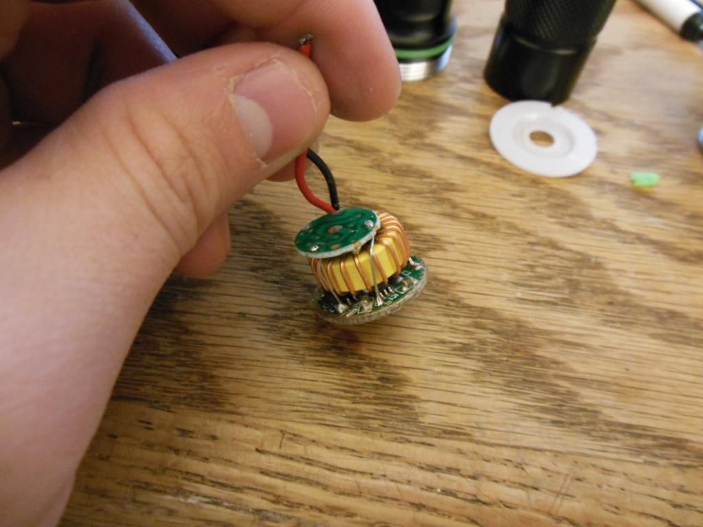
Is the driver in the pics in the post above look like the one you had? Seems like the one I have might be resistor moddable if it’s just that already stacked one?
Thanks. I was going to ping you (you’re like “the buck driver guy” to me now :)!). The resistor is larger than the ones on the 17mm drivers I have, so I’ll have to hunt around for some. If not, would soldering the smaller resistor on top of the stack work?
Maybe another R200 (probably the closest I have to an R180) or an R100?
I have 4 , 2 SMALL SUN , REF is about 35mm Deep ,and a large AL Pill. And a AL Retaining Ring holding Driver. ———— 2 SIPIK HK70 REF is 42 mm Deep, smaller Brass Pill , 22mm Driver Soldered to Pill.
I’m not thinking of shorting the stack resistor. I think that would put the light into DD, i.e…, putting 8V across the emitter, which is probably what blew the LED up (might’ve been ok with an MT-G2, though :)!).
You’ve just described normal operation for a buck driver. Now you know!
You’re welcome. IMO you need to unstack the resistors to determine the current value. (Unless of course we know what the buck controller is, then we can make an assumption as to the current value of the ‘bottom’ resistor in the stack based on spec’ed sense voltage.) It’s probably QX9920 like so many of these, but I can’t see the markings on it in the picture.
The package for the sense resistors does not matter a lot, but it matters a little. Maybe it’s a 1212 package? Are they twice as wide as your 1206 and just as long? You just want to keep dissipation on each resistor in a reasonable range, but since they are stacked like that “a reasonable range” is probably a little lower than normal. I forget what they’re normally spec’ed at, maybe 0.5W each?
Also, I’m just curious, but what is the logo on the FET?
Hi Ohaya. That driver looks like it has the potential to push a lot of current due to the size of the inductor and large diode. I'm just going off their physical size (not looking at data sheets).
With so many unknowns, one has to guess what you would need to add to get to the current you want. You could just clip on an R200 and see what impact it has and then go from there. Otherwise, we need to know:
Current to the emitter on high
Value of the resistor under the top resistor
Or,
Voltage drop across the sense resistor bank when the light is on.