I’ve had this black SRK light since December 2013 and just decided to open it up today.
Ever since I purchased it I have been extremely disappointed with its output.
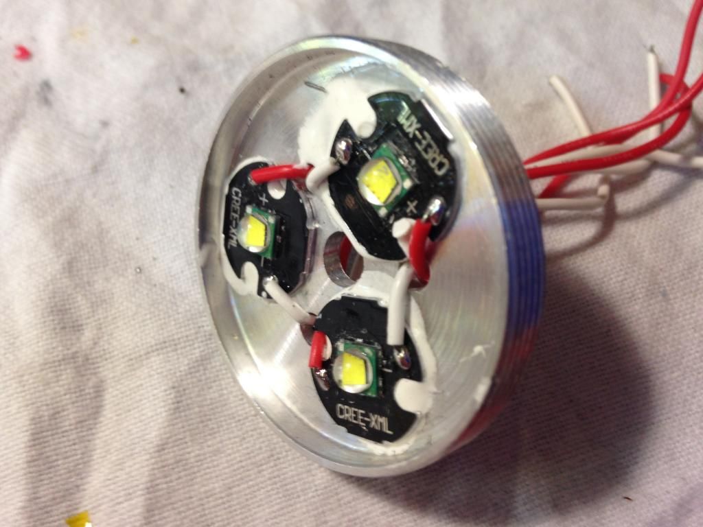
Although I was pleased to find that it has a solid emitter shelf
So far I have braided all the springs and changed the led wiring to thicker 22 gauge.
How should I go about resistor modding this driver?
Upon searching around BLF I found that OL has modified this exact same driver \\\\ In this thread.
Although it looks like he swapped out resistors for different values but I don’t have any other resistors, should I just bridge the lot of them? J)
I am not worried about frying the leds nor the driver. I am going to order xml2’s on noctigon along with a SRK fet driver from rmm to replace the stock innards. So this mod is merely for the sake of practice and to see how much I can currently get out of this light before it blows up (Hopefully not literally).
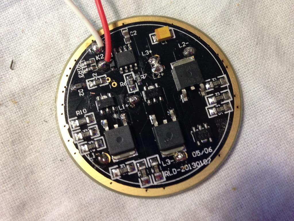
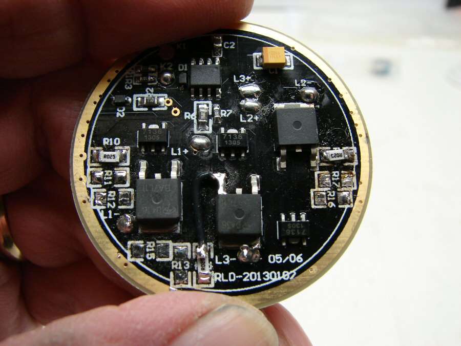
This driver is somewhat similar to the driver used in the Supfire M6. Both are 3-channel linear drivers using a QX7136 to control each channel. It seems that this driver (RLD-20130187 or RLD-20130107?) is using AOD436 rather than DTU30N02 for the MOSFETs though. To me it looks like AOD436 is a very poor FET for this application: it has a high ‘Rds(on)’ (aka restance) value at the gate voltages we are likely to see. It is much worse than DTU30N02.
Bypassing the sense resistors will just give you DD. DD will be poor due to the AOD436’s poor performance at low Vgs (aka gate voltage).
Depending on your goals I recommend an FET swap. The driver may require piggybacking a new MCU after an FET swap, depending on what you swap in and what frequency the stock PWM is.
You could also just piggyback an entire FET driver for DD, but you will not be able to get really low moonlight levels that way.
I wouldn’t purposefully try to harm those LEDs (what would be the point?), so I’d try to keep drive currents at 2A to 4A each due to the stock aluminum non-DTP MCPCBs. If you transplant them onto DTP boards such as Noctigons, SinkPADs, or Maxtoch DTP boards you can do higher currents without fear. If the light starts to look more blue than it did before, the emitters are very very unhappy.
In order to keep drive current in check a resistor mod would be a good idea! If you want to get into modding you’ll end up needing sense resistors anyway, see my links below for cheap ones. The correct resistance is easy. For each controller the “sense voltage” is a known number, in the case of the 7136 it’s 0.05v. You take that voltage and divide it by the current you want that channel set to (say you wanted 5 amps, you’d do [0.05 / 5.0 = 0.01]. The result is the total resistance you need. From there you’ll need to work out the parallel resistance required to get it. A parallel resistor calculator like this one comes in handy: PARALLEL RESISTOR CALCULATOR
We can also work that math backwards to determine the stock “set current” the driver came with… it’s got 3x R100 (the R is a decimal point), so our calculator shows 0.033333 ohms. [0.05 / 0.033333 = ~1.5 amps] No wonder you were disappointed.
When I first inspected the MOSFETs on the driver they looked very similar to the DPAK sized FET such as the Vishay 70N02 although obviously they are not the same.
From your calculations you concluded that the drive current on the stock driver is ~1.5A. Is that overall or is it for each individual MOSFET channel? (Ie 1.5 amps per led).
I am not intentionally trying to fry the leds, I was merely pointing out the fact that I wouldn’t be too concerned if it were to happen. (Not to say that I shouldn’t excercise a certain degree of common sense ;))
You’re welcome. Yes, it’s they are N-channel MOSFETs in the DPAK package. Vishay 70N02 (SUD70N02) would definitely be an improvement at higher currents if you have those laying around. (They are no longer available.) Otherwise maybe look at AOD510. AOD510 is probably better anyway.
Note that I did not only give you instructions on doing the set current calculations yourself, but also walk you through the calculation I did step by step to reach 1.5A. What part did you not understand? The channels are independent and the calculation I showed was for a single channel. (Hence the calculation only dealt with 3x R100 rather than the 9x R100 which are present on the PCB…)